Revell Easy Kit 06690 Star Wars X-Wing Fighter
(435mm Long)
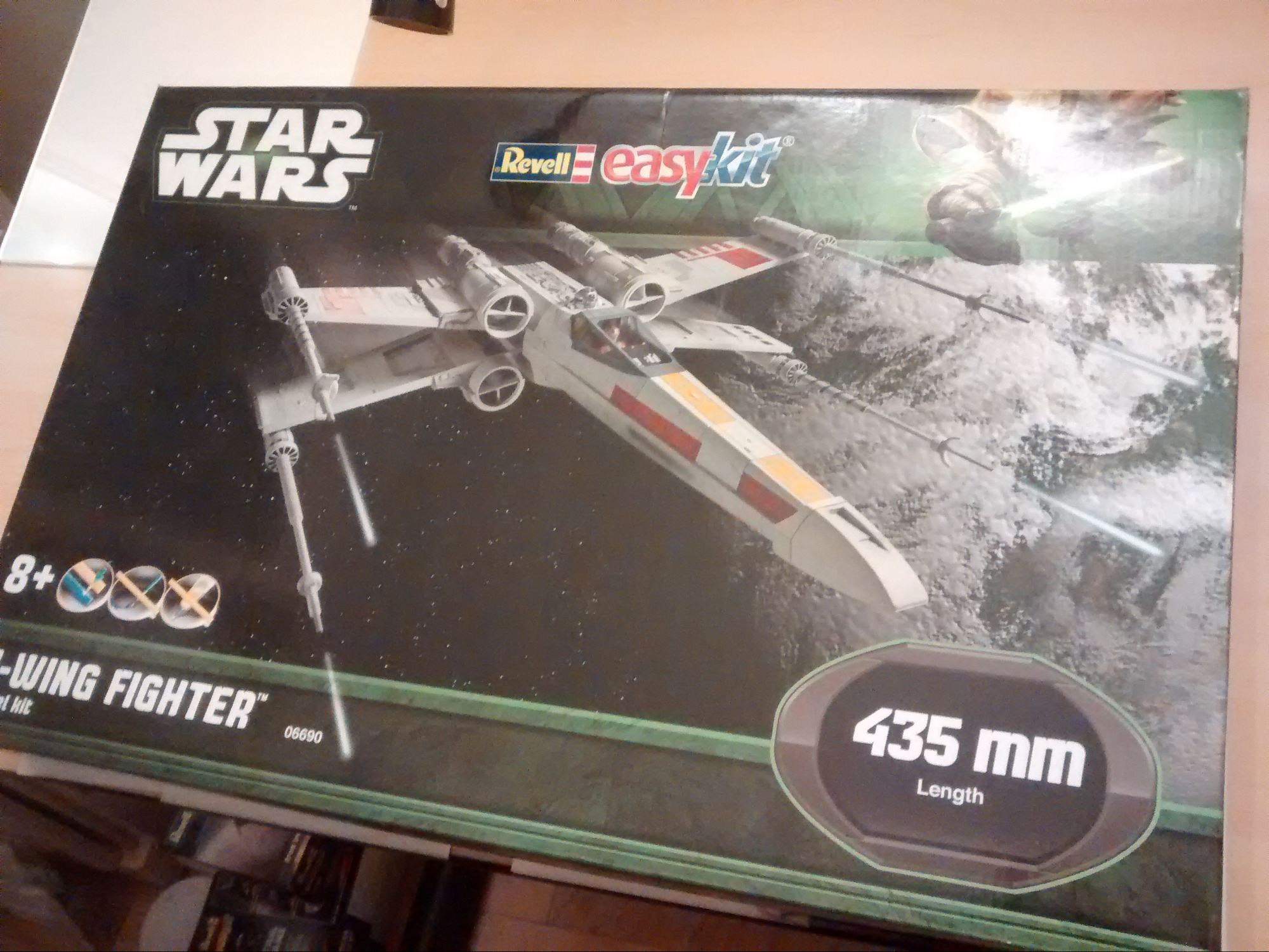
We've now reworked the X-Wing Light Kits to make them more effective and easier to install. We'll start with one of the larger scale Revell craft - the 06690 435mm...
Step 1
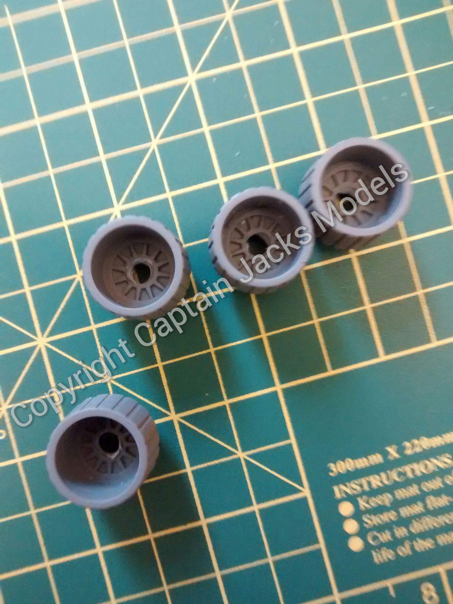
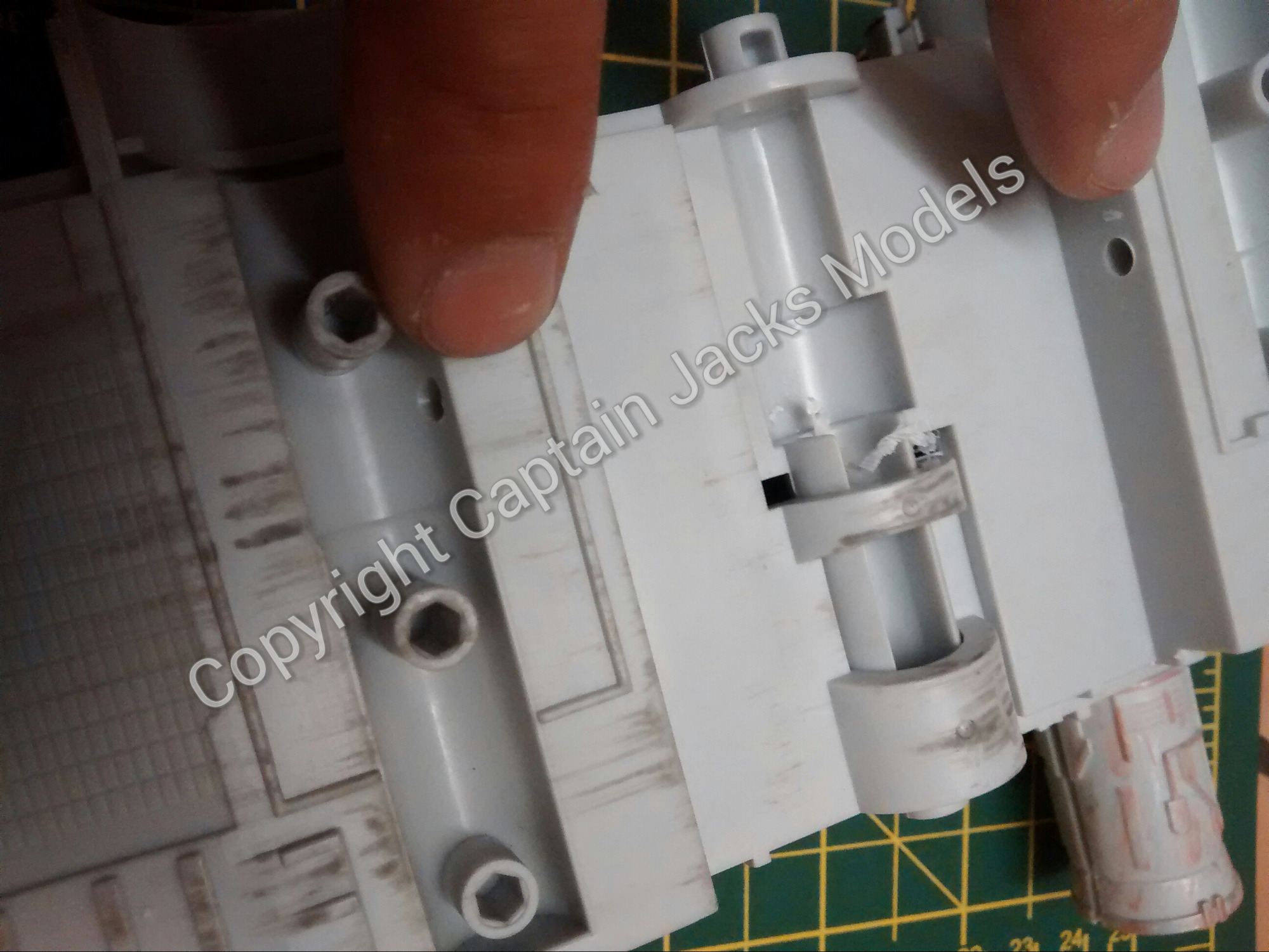
Start by drilling 5mm holes in the centre of each of the four booster section.

Step 2
Drill 3mm wire run holes in each booster section unit as shown.

Step 3
Piece the two parts of each booster unit section together. Again, drill 5mm wire run holes in the end of each section that secures the end of the booster unit.
Step 4
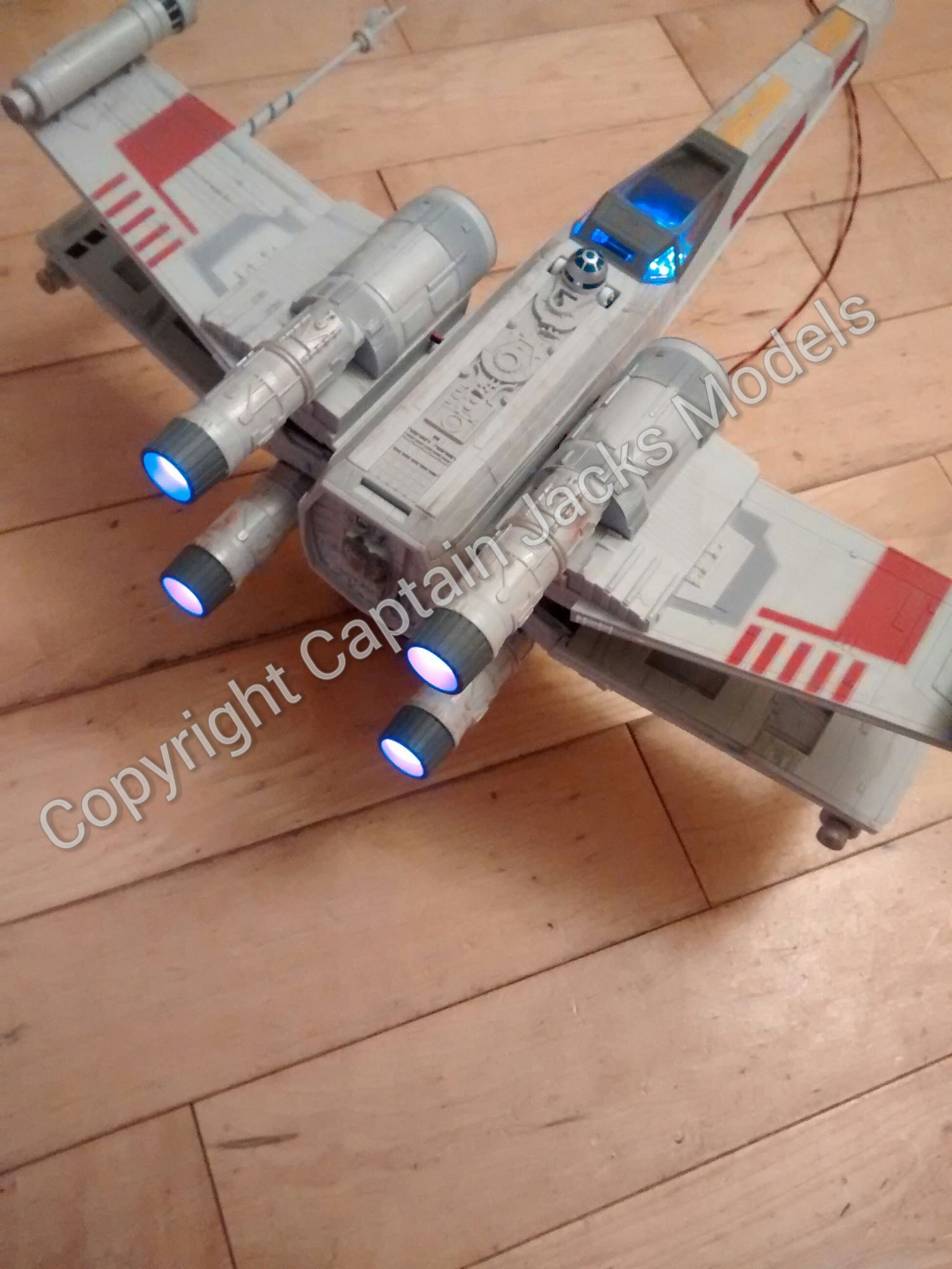
Fit each of the pink booster leds individually, routing the wires as shown.
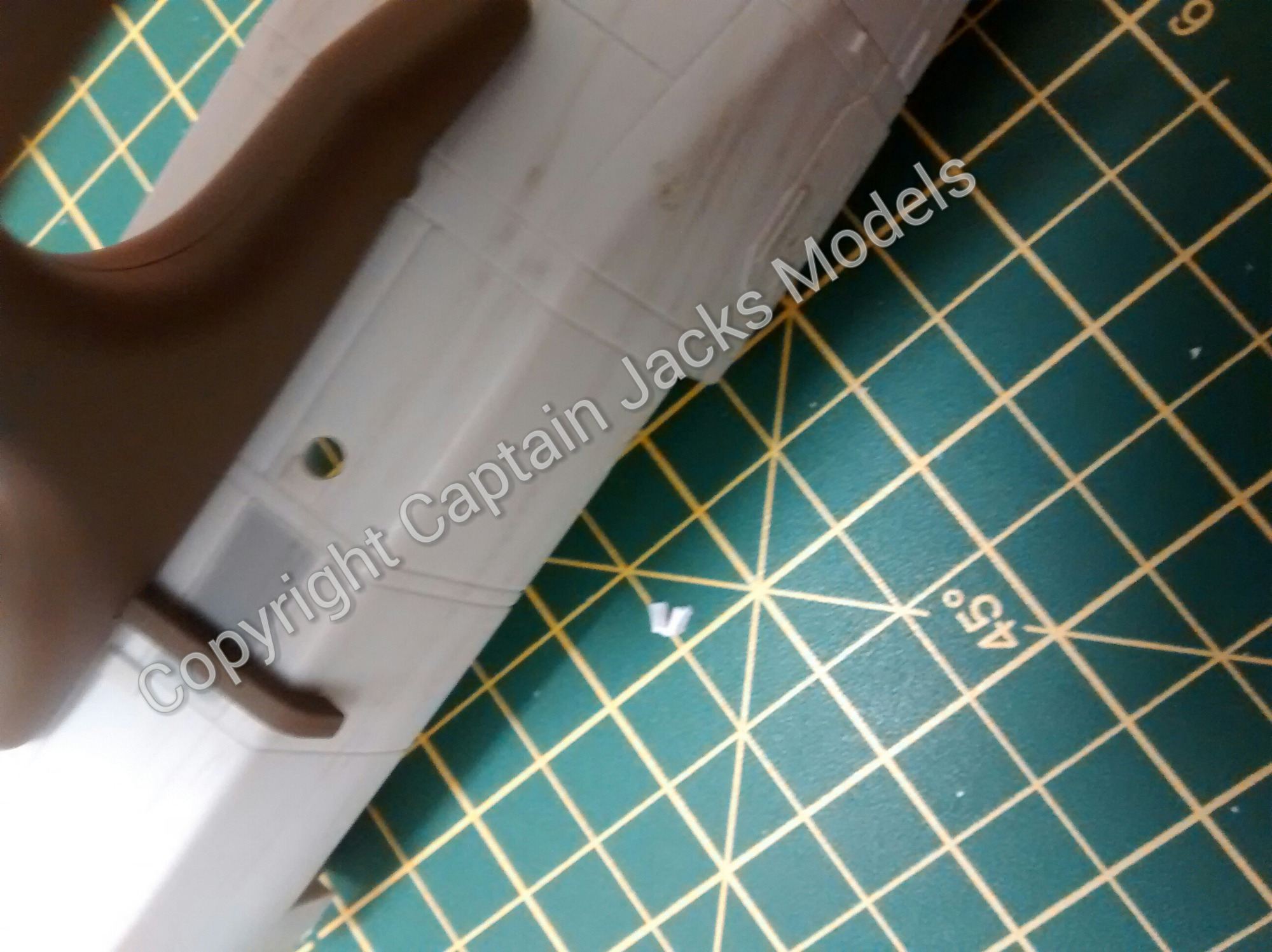
Step 5
Assemble the two wing sections as per the model instructions. You then need to drill two 3mm wire run holes as shown in the inside of each wing section. The booster sections can then be fitted, and the led leads run through the inside of the wing.
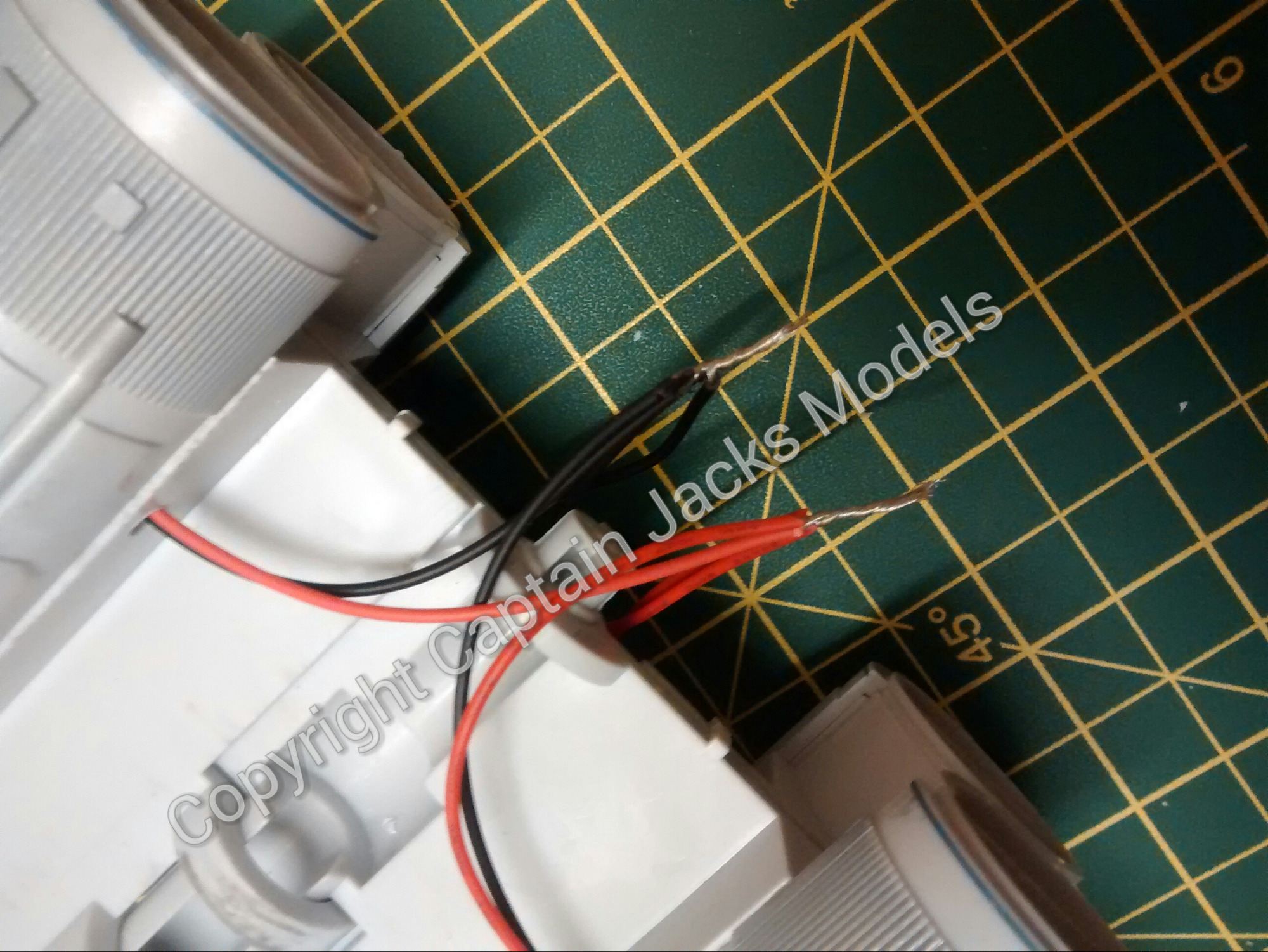
Add the assembled booster unit to each wing section, and route the led wires through the inside of each wing.
The led wires now need to be joined together. Simply twist the four RED wires together, and seperately twist the four BLACK wires together as shown.
Step 6
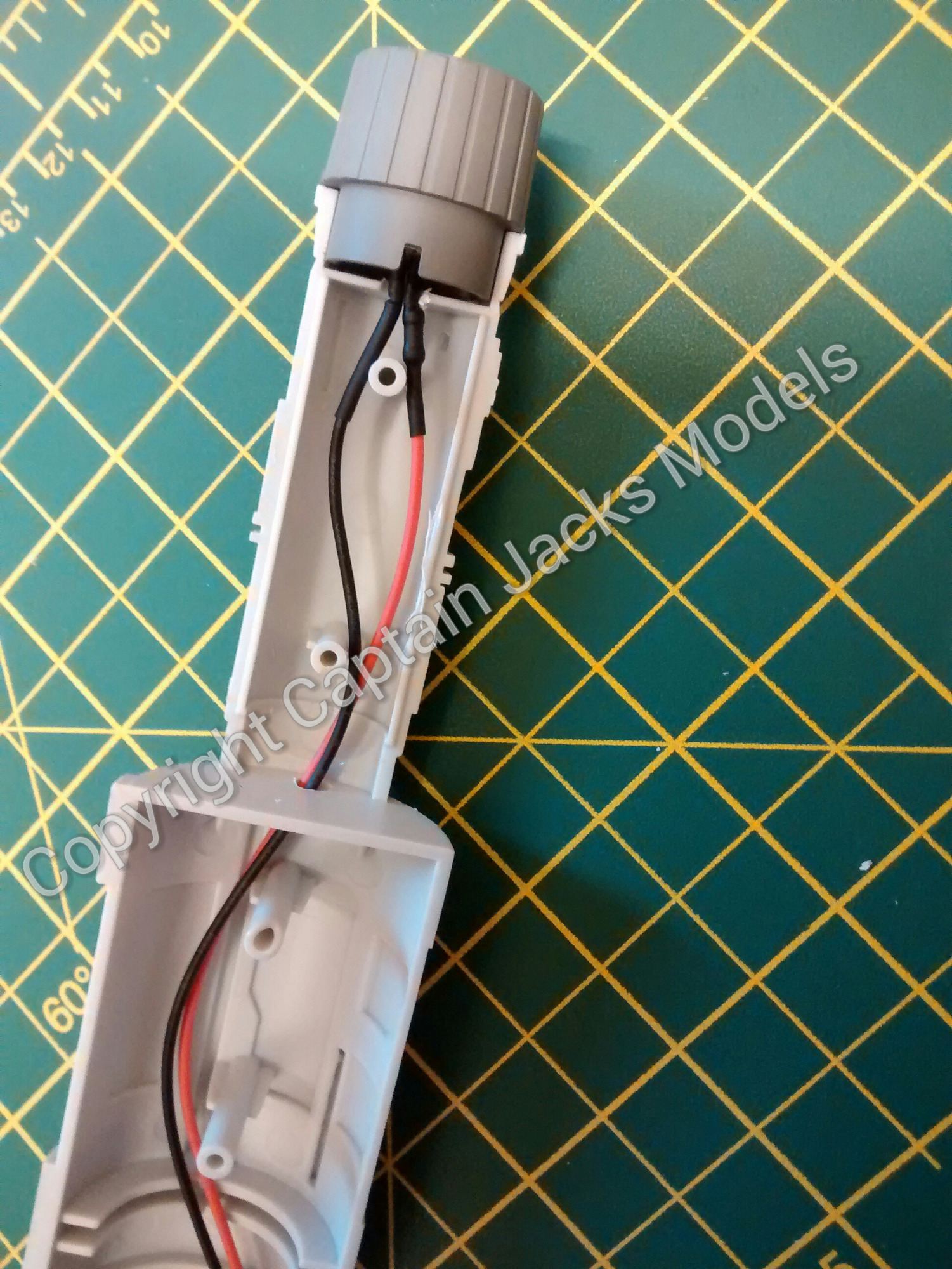
Drill a 3mm main power lead hole in the bottom of the fuselage. This should be in front of the wing section at the centre of the craft.
Step 7
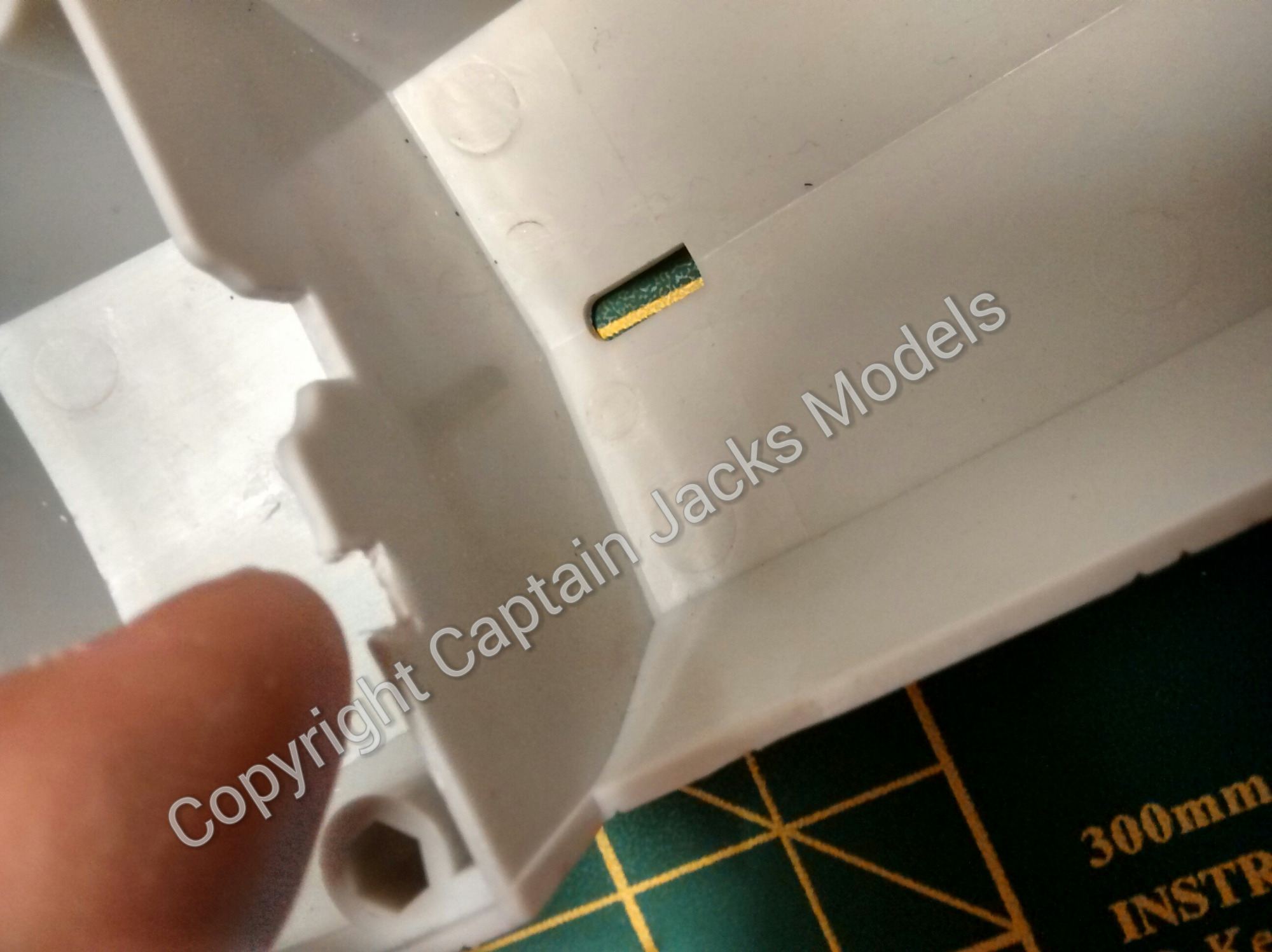
Cut a small notch, approximately 4mm square, in the front divider that supports the wings. This allows you to run the booster wires through to the cockpit area.
Step 8
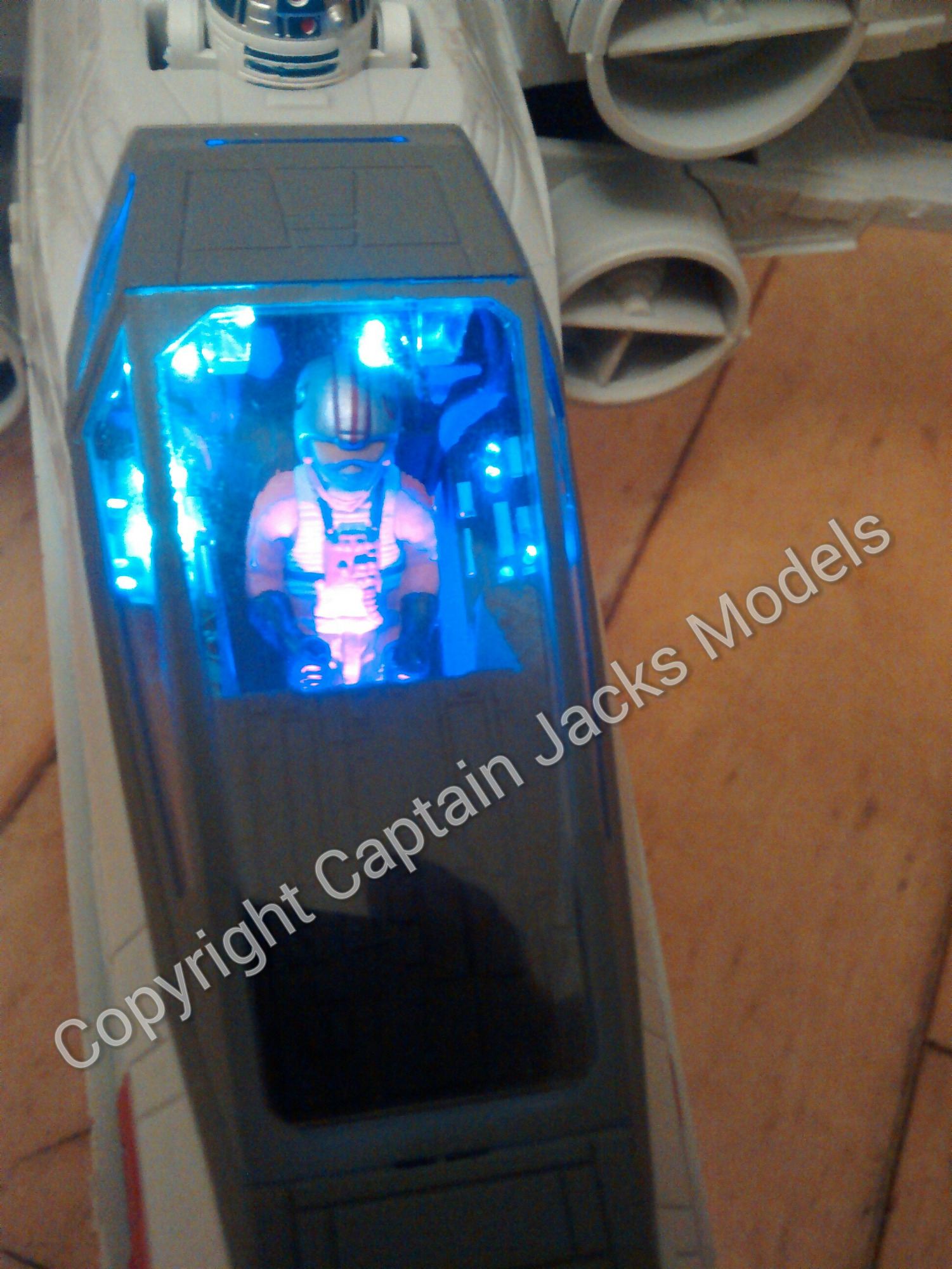
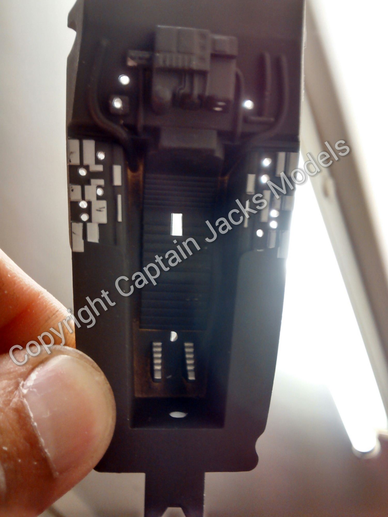
It's now time to start installing the cockpit lighting. On the cockpit interior section, drill x15 1mm holes for the fibre optic strands. I have used the layout shown, but the fibre positions are entirely your choice.
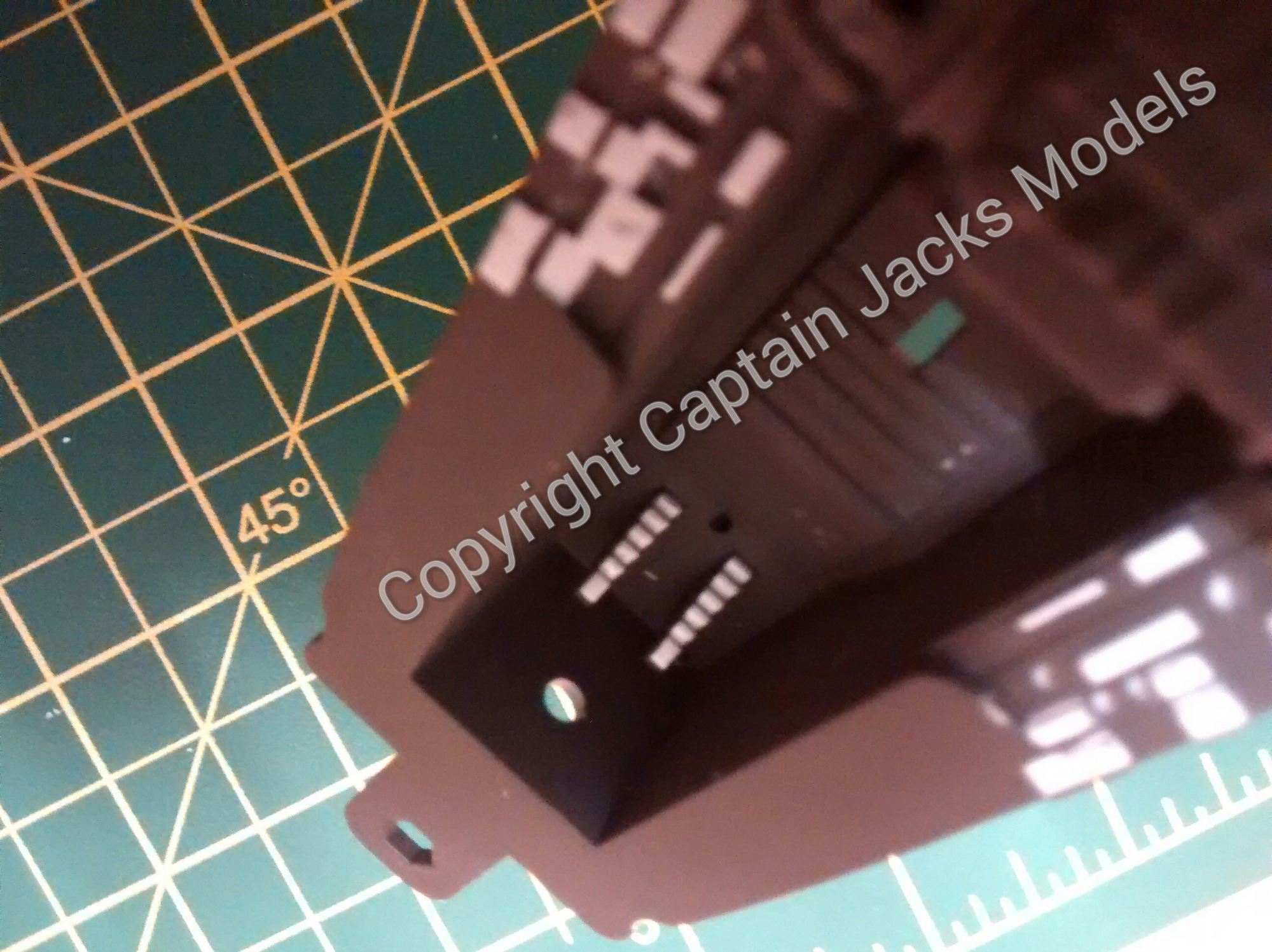
Drill a 3mm hole in the front of the cockpit section next to the pilots feet for the ultra violet up-lighter.
Step 9
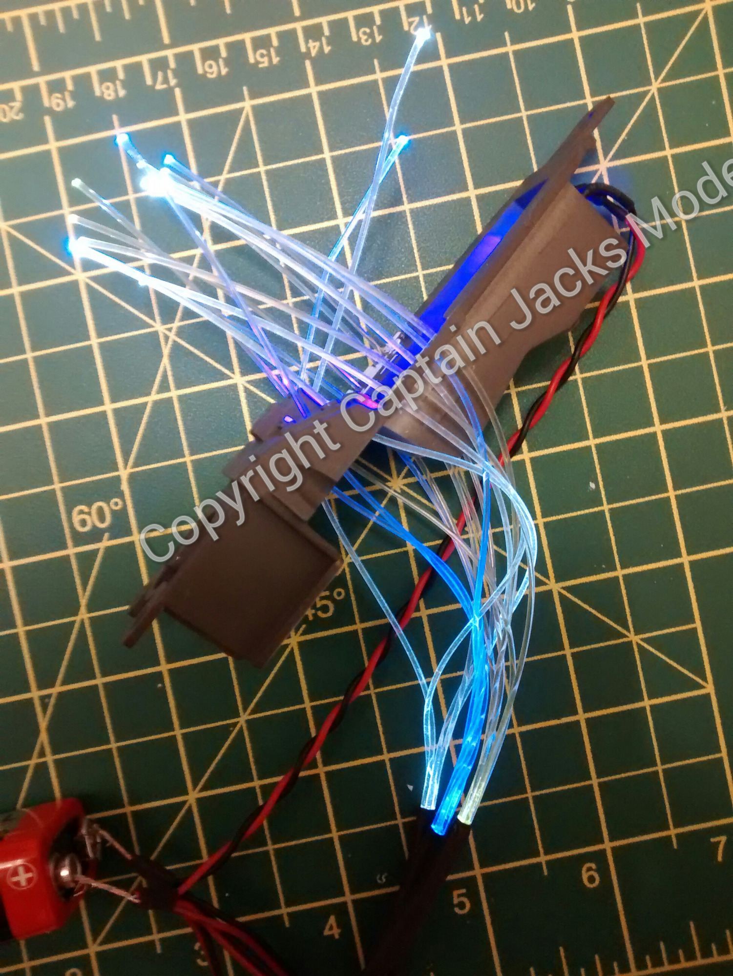
Install the fibres from each of the three fibre optic units in your chosen positions. Try to mix the colours in each section, and group only two like fibres maximum together in any area to give a random effect.
Pull each fibre through carefully around half way, and install the 3mm ultra violet led up-lighter. Test the colour effect with the 9v battery if required at this point.
When you are happy with the light layout, secure the fibre optic strands on the underside of the cockpit section using small drops of glue (I tend to use super glue). It is also worth securing the uv up-lighter with a glue as well at this stage.
Allow the glue to dry fully, then using flush cutters, trim each strand so that it is level with the console panels on the cockpit unit.

Step 10
We now need to join all of the wiring from the cockpit area and the boosters together. To do this, twist the RED wires from the cockpit fibre bundles together with the RED wires from the boosters.
Now twist the BLACK wires from the cockpit area to the BLACK wires from the boosters. Screw both wire bundles together into one side of the screw terminal connector as shown.

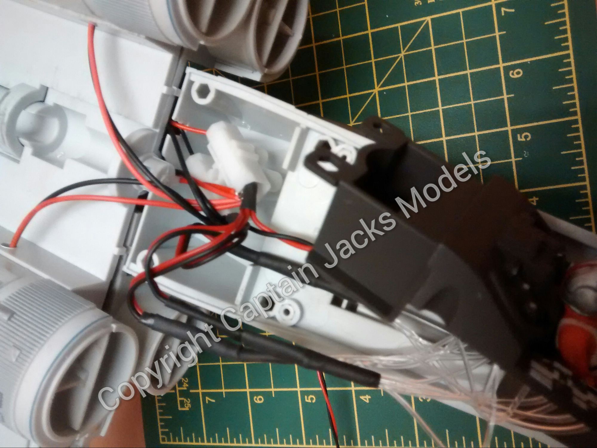
Step 11
Run the power lead through the hole in the bottom of the fuselage to the opposite side of the screw terminal connector, joining all red wires together, and all black wires together (including the two on the power lead). Secure all connections and test with a 9v battery.
Step 12
Continue to assemble the model as per the instructions. Tuck the excess fibre optics underneath the cockpit, and the screw terminal connector in the gap in front of the wing unit. Thats it - all done!