The Bandai 1/144 Falcon
This one is a great model - and when it comes to model lighting, is one for those who relish a bit more of a challenge. My main aim with most of the light kits is to make it as easy as possible for people to achieve professional results with both the minimum cost and skill level, and so I've put together two light kits for this model. The first is a basic set which is much easier to fit, but still provides considerably more lighting than the bandai set itself. The second is the more interesting but challenging. Read through the step by step guide to see which one you're most comfortable with.
Let us begin...
Start by assembling the two halves of the model as per the instructions. As with the other Falcons, it's the base of the model in which most of the lighting is installed. With the two halves of the model more or less completed, now is also the time to consider a base coat for any colour washing for the weathering if required.
Your best friends for the modifications needed will be a 1mm drill, 3mm drill, 5mm drill, flush cutters and some good tin snips.
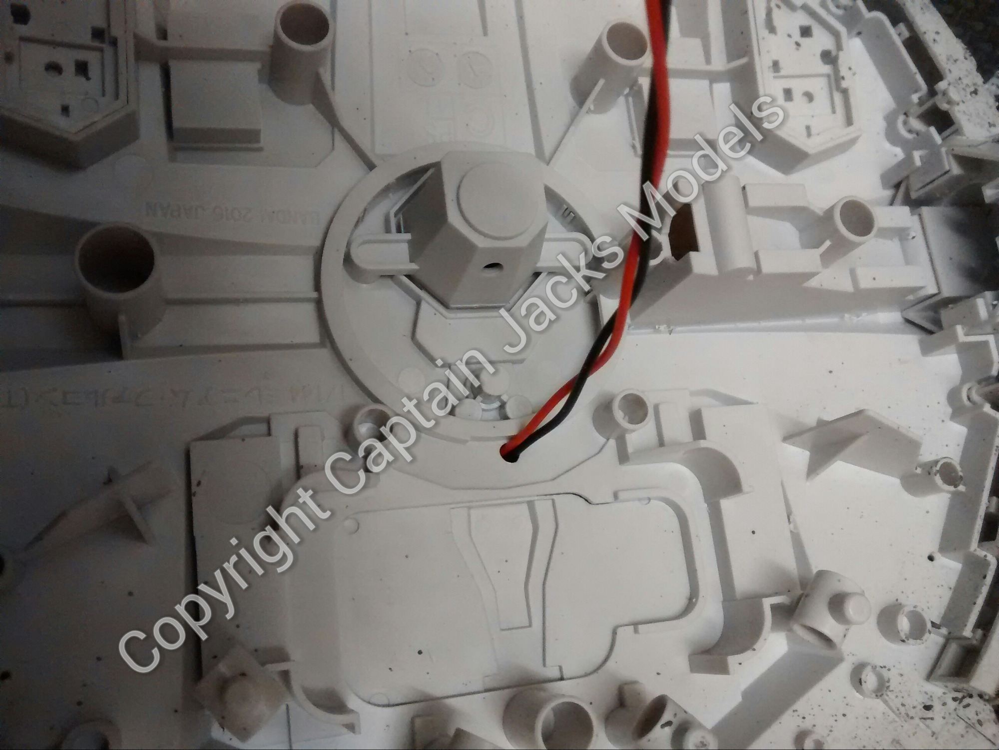
Consider how the model will be supported (eg using the stand supplied or a modified stand of your own), and drill a 3mm hole through which to run the main power lead - the light kits can be taken apart at the terminal connector to allow this to be run through the model.
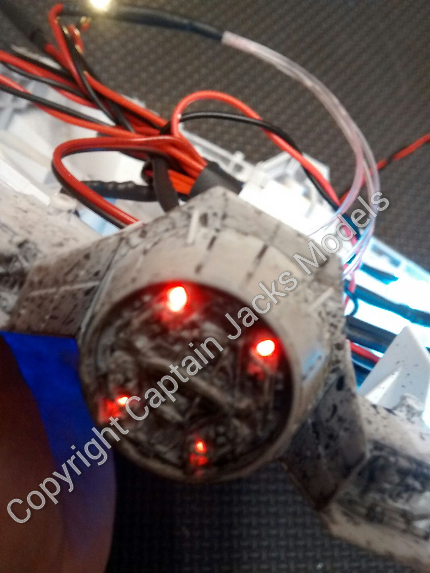
Once done, the led supports supplied in the kit need to be widened to 5mm - carefully, preferably by securing them in a vice and not drilling through your hands (getting blood stains out of the colour washing can prove tricky) - and fit these in place on the rear engine mounts.
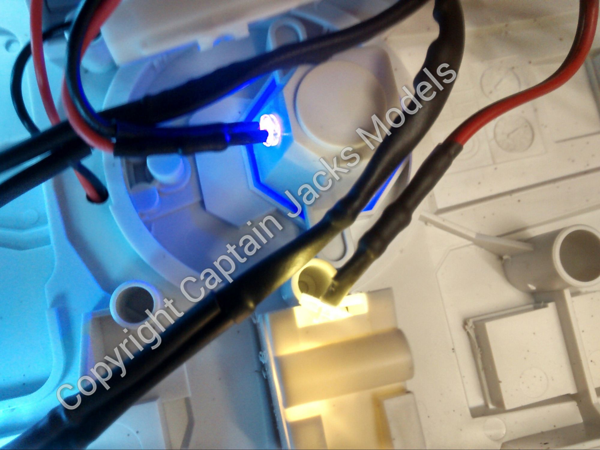
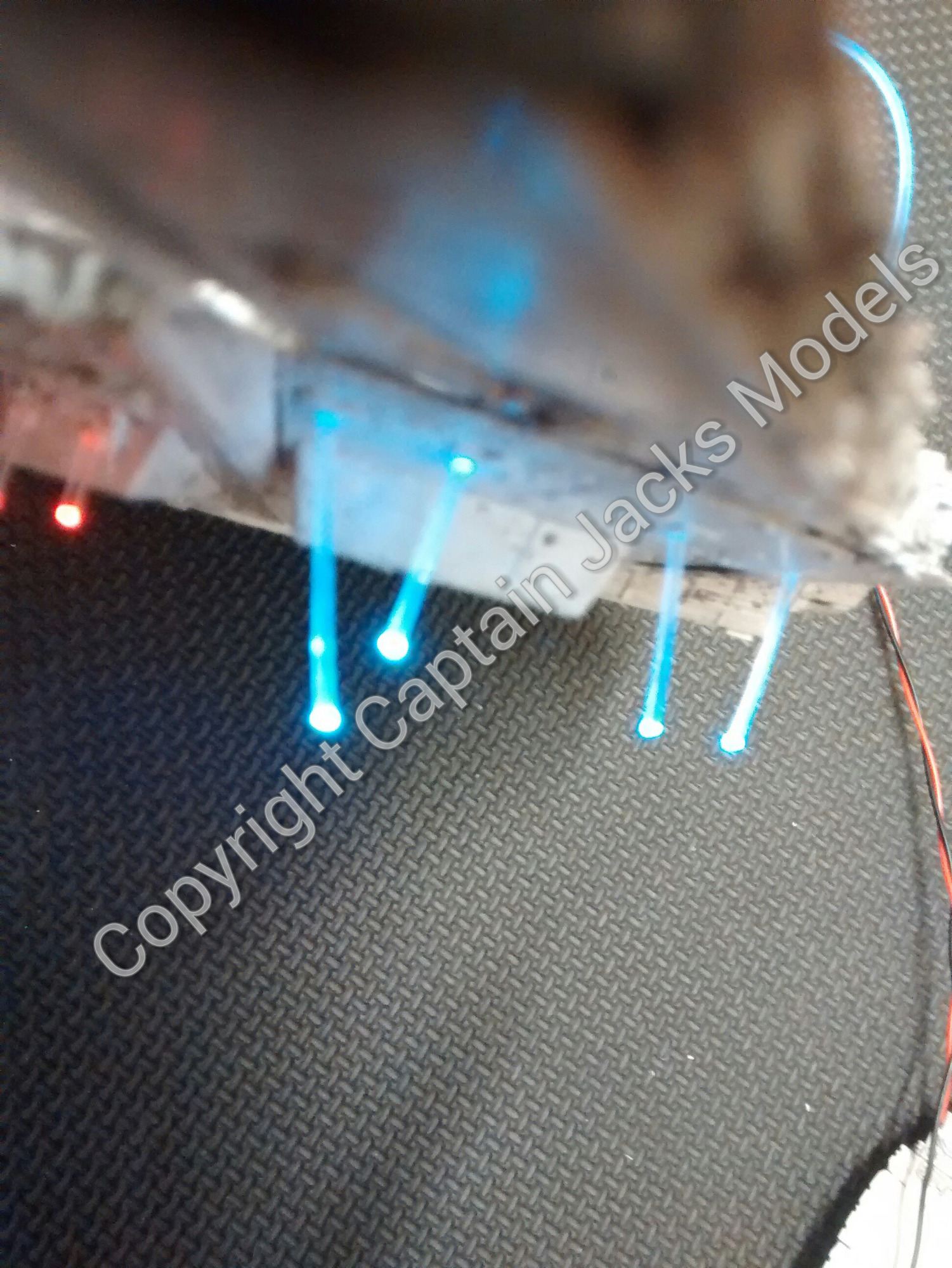
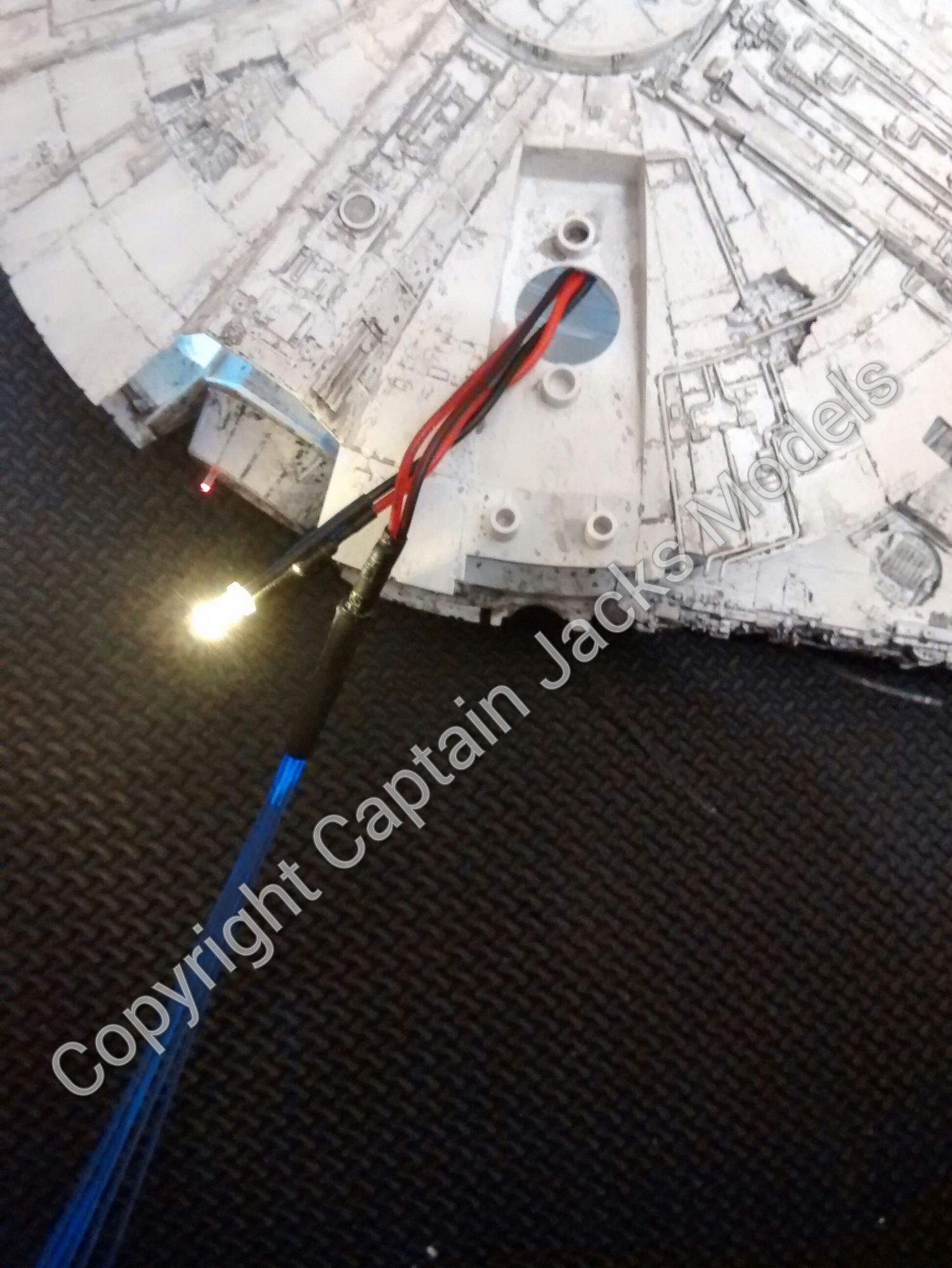
At this point, it's time to change from a 5mm drill bit to a 3mm. Using the 3mm, drill the fitting holes in the upper and lower centre sections of each panel for the warm white and ultra violet lights. Its best to have these leds facing horizontally as opposed to shining straight down through the clear section to avoid the radioactive glare - see the photo for details.
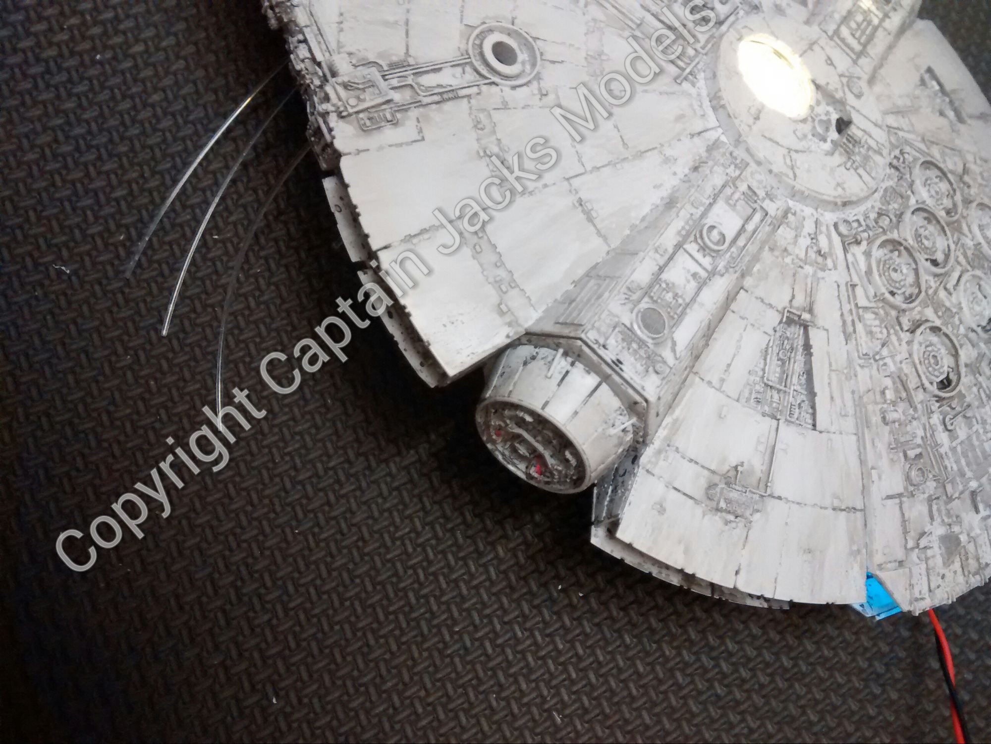
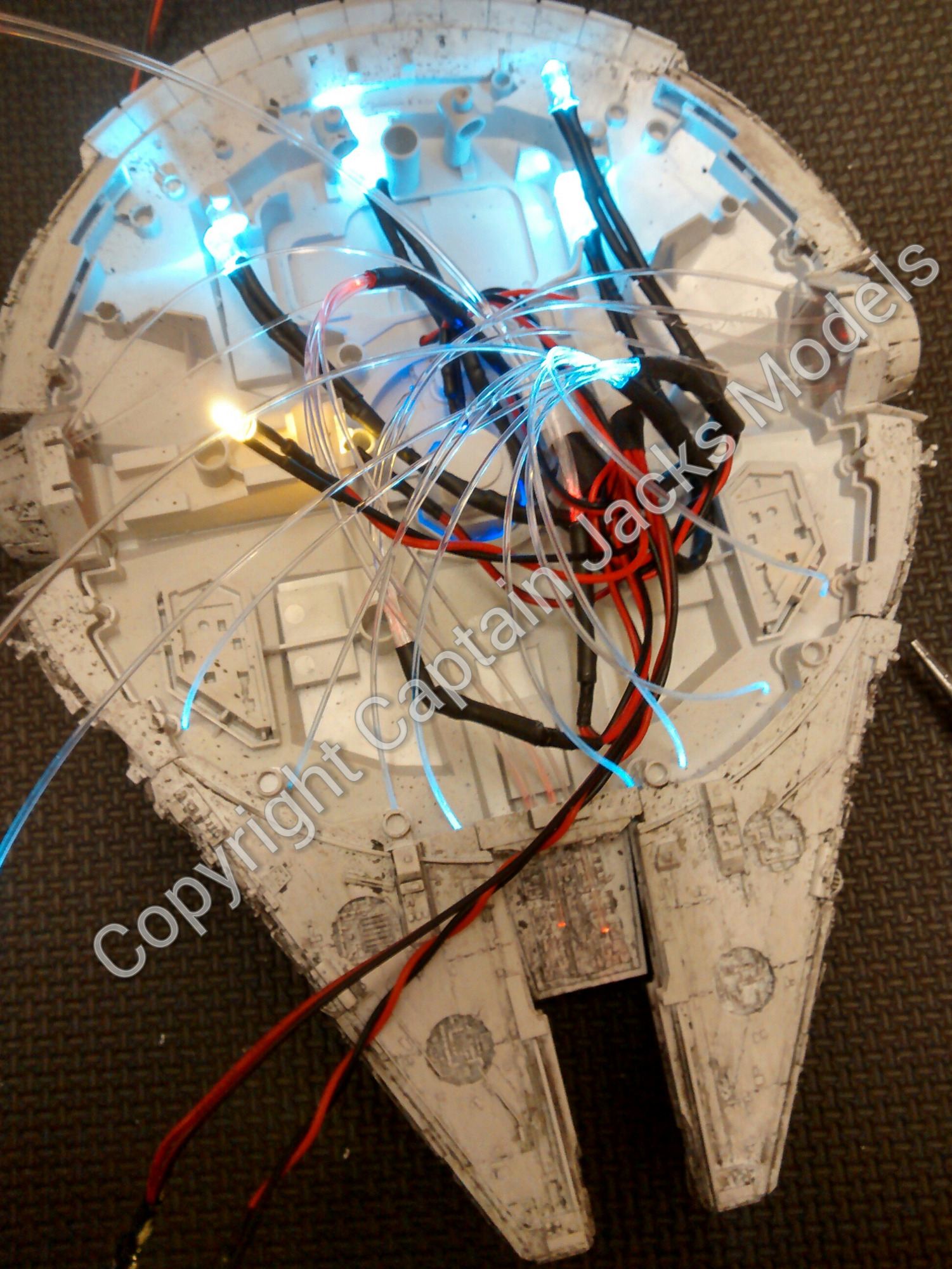
For those who have opted for the basic light kit, that's most of the modifications out of the way. For the more sadistic amongst us, it's time to change to a 1mm drill bit and look at where you would like to fit the fiber optics in the main body. I started with the red fibers - four on the left hand section as per the photo, four on the front central section, and finally two on the right hand section (it is possible to get the four here aswell, but is dependent on what you intend to do with the ramp section and is very fiddly to do). Again, see the photos for better understanding.
The flashing white fibers, I installed on the base in the semi-circular pattern. If you look at the outer side of the bottom section, you'll see four small "panels" on either side which are ideal for these light positions.
Time then, to start installing the light kit...
1) Take the kit apart to allow the power lead to be run through the model, then re-assemble.
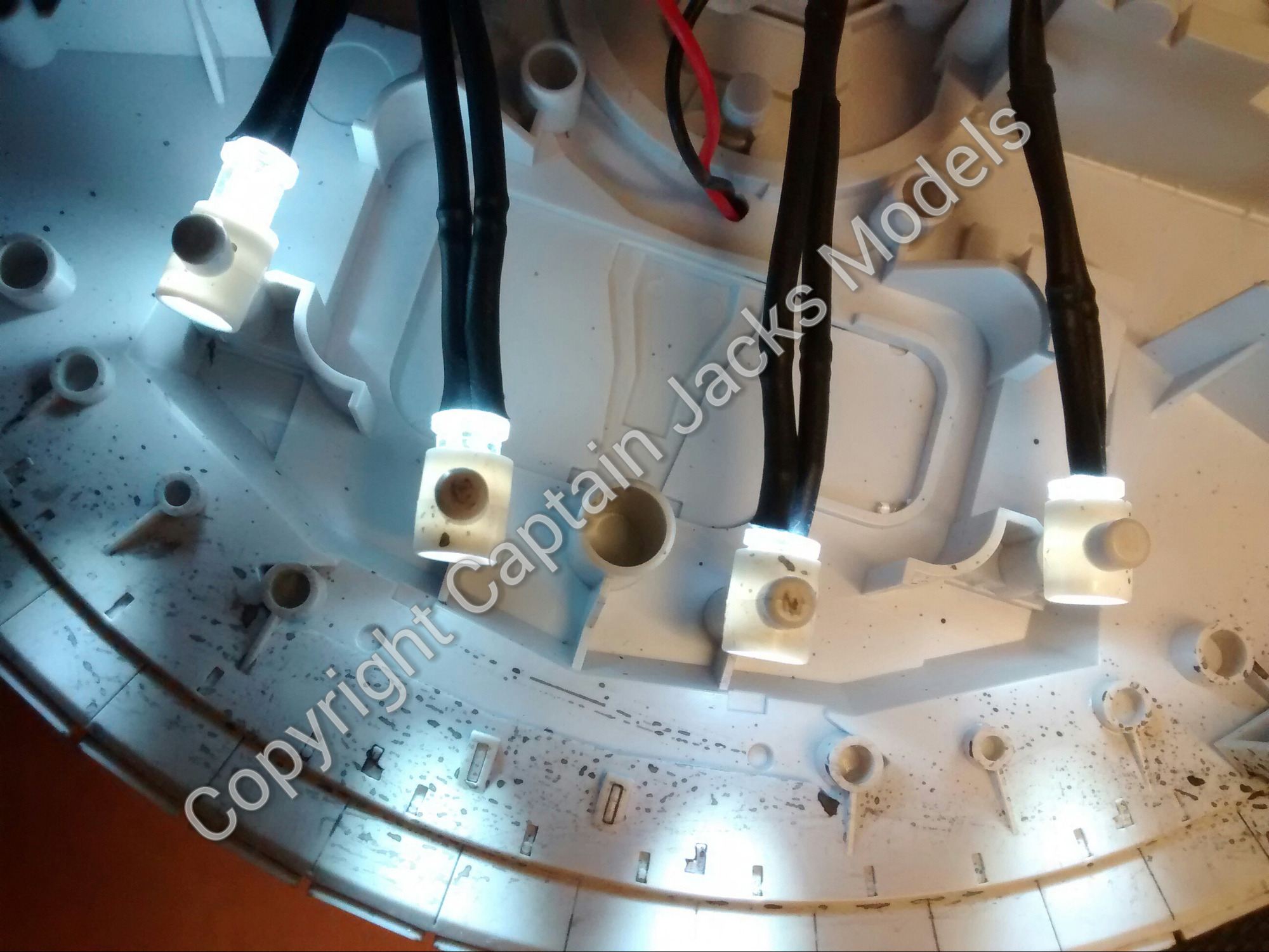
2) Place the booster lights into position - these will need to be glued into place with a drop of pva for secure fit. Angle the holders so that the beams cross and diffuse the light more evenly.
3) Fit the 3mm ultra violet in the lower central section, and the 5mm warm white in the walkway aperture if required (secure both with pva)
4) Start with the red strands. Position them in the side and front sections as required.
5) Next it's the flashing white strands. If you've opted for the semi-circular pattern that I favour, you will need to mix the fibers. By that I mean that you don't want have of the fibers on one side of the ship flashing all together, so start from the left and alternate one fiber from the one led unit, then a fiber from the other white led unit etc. This way as the flash rates go slightly out of sync, you get a twinkle effect instead of a block of lights flashing together.
6) Pull all of the fibers through so that there's plenty excess fiber on the external part of the base section.
Time for the faint hearted to shut their eyes....
Time for the faint hearted to shut their eyes....
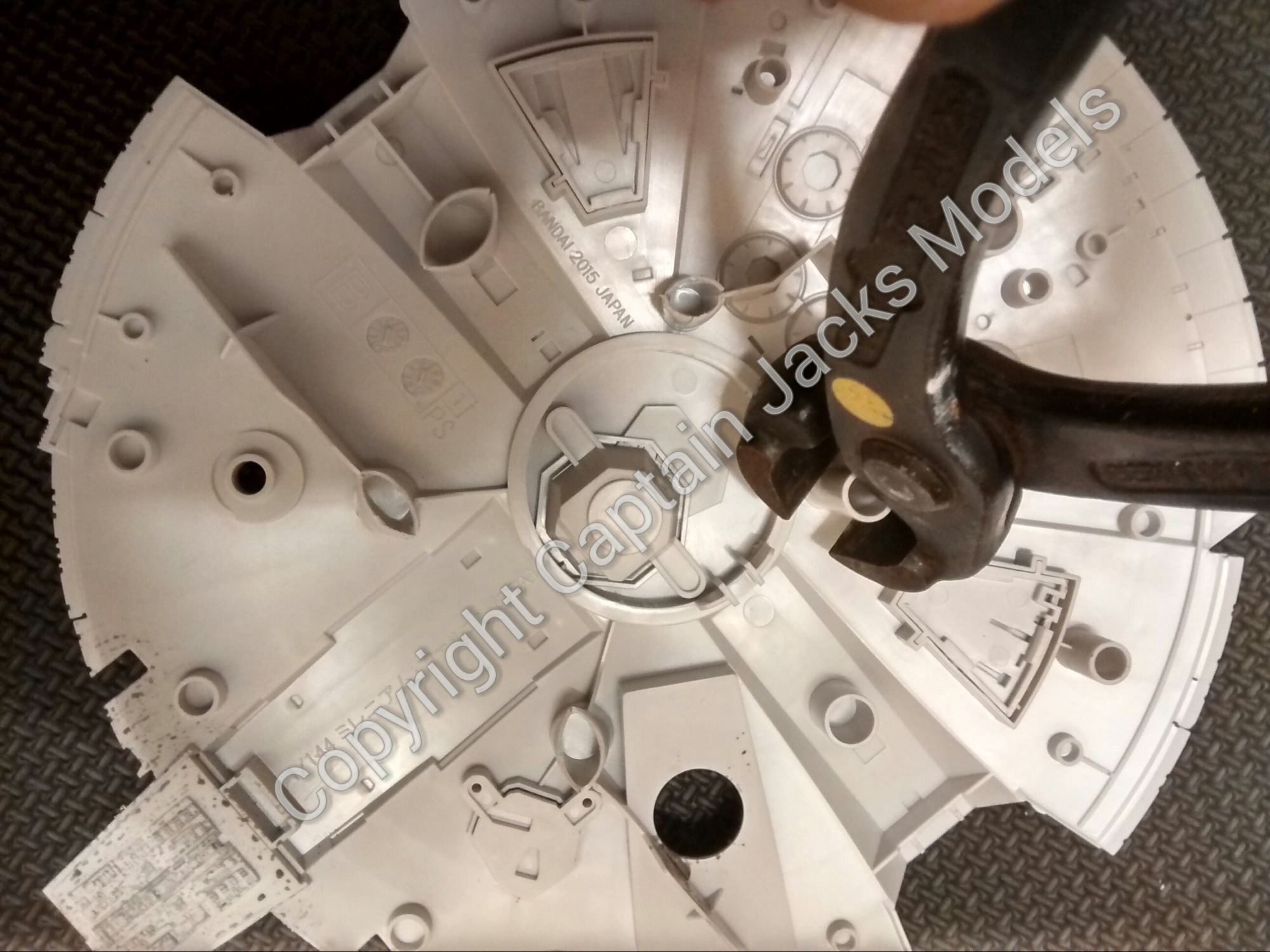
I'm guessing that by now you're wondering exactly how all of the wiring and fiber optics are going to fit into such a small space. Well that is what the tin snips are for. On the upper panel, there are eight plastic struts - the ones which protrude the most - that need to be clipped in half to allow the wiring to fit. Do not attempt to remove them completely, as it will damage the outer section of the model. Trimming in half is plenty. The model will still clip together using the outer securing points.
Now at this point, check that everything on the light kit is working perfectly.
7) Pull all of the fiber optics through the shell to get a good fit. Place a small blob of pva on the inside of the panel where each fiber runs through to secure them. Also ensure the other lights are secured with pva just to make sure.
Now, leave it for the day to let everything dry. Patience is a virtue :)
When everything has thoroughly dried, fit the booster grill section as per the instructions.
It's now time to fit the upper and lower panels together. Before you do this, fit the 3mm warm white led in place in the central section, and pva to secure. The 3mm warm white and colour changing fiber unit need to be fed through the large hole already in the top panel that leads to the cockpit section.
For the cockpit area, you can go into as little or as much detail as you wish with the lighting. The warm white can be suitably positioned to provide a general or background light which in most cases is enough to showcase a bit of detailed paintwork, whilst the fiber optics can be used here too if required. Again, 1mm fitting holes for each fiber as needed.
Finally.....
8) When you're happy with each of the panels, fit them together and trim each of the fibers to a neat finish using the flush cutters. That's it - job done!