
AMT 1:25 Batwing
The Cockpit
The AMT Batwing is the perfect example of a model where when lighting is concerned, less is more. Over the years I've made many variations of this kit, some with extra landing lights, others with intricate fibre optics for the control panels etc, but for this model the majority have never swayed my preference of simple being the best.
For this reason, this light kit features only the two wing lights and an ultra violet cockpit uplighter to pick out the details of the Batman figure. The model kit itself is supplied with a nice night-time cityscape backdrop. If you find yourself tempted to add even more lighting to the build, it's worth looking first at what you can achieve with uplighting from the backdrop rather than adding to the model itself - you can get some surprisingly better (and easier) results this way.
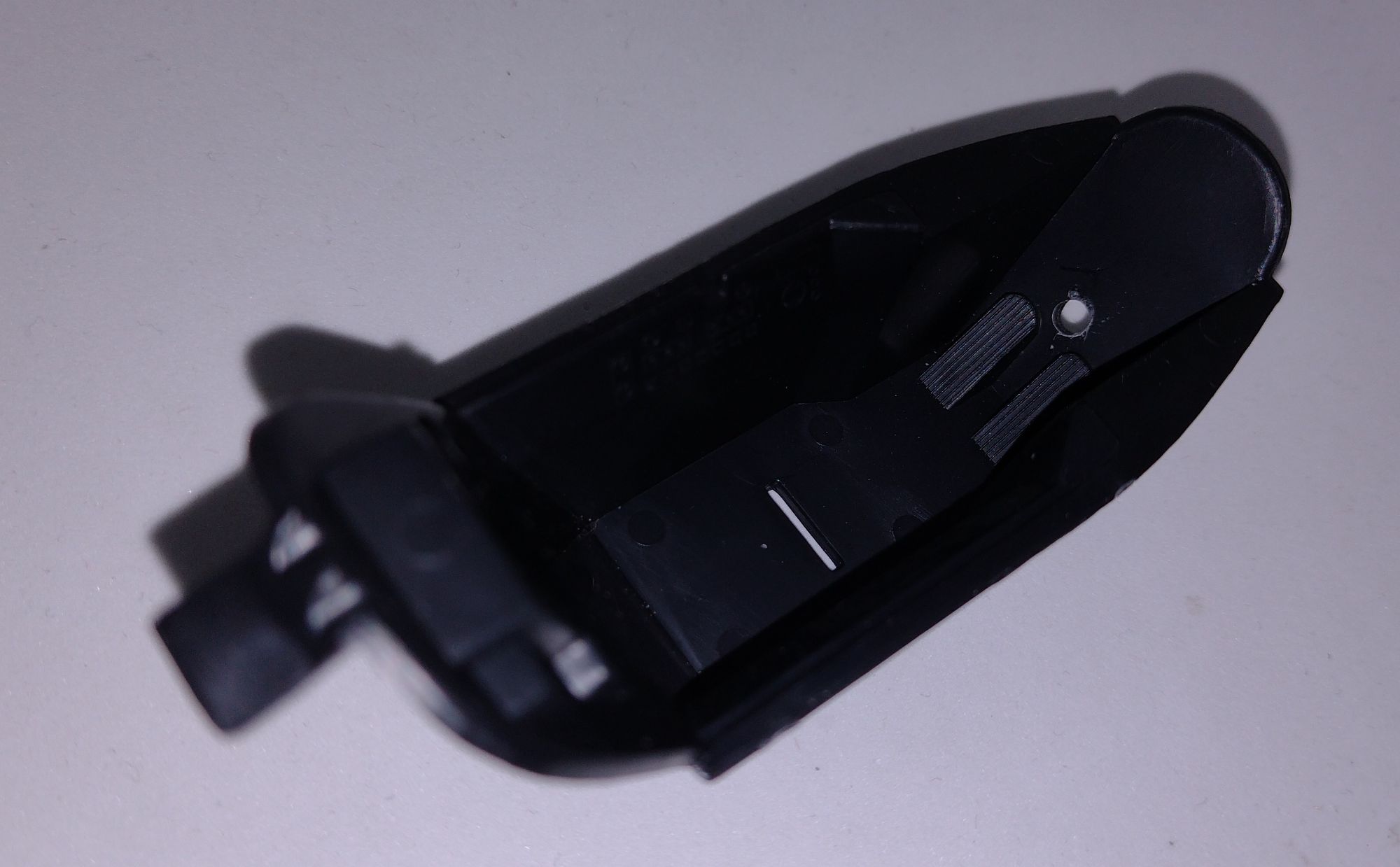
With only three main lighting components, installation of the light kit is pretty straightforward, and the model kit itself is quite easy to modify. The first modifications needed are 3mm drill holes: one in the cockpit footwell as shown for the UV led, another in the lower fuselage section where the metal stand will slot in, and finally in the base - again at the other end of the metal support stand through which the power lead can be run.
Wing Lights
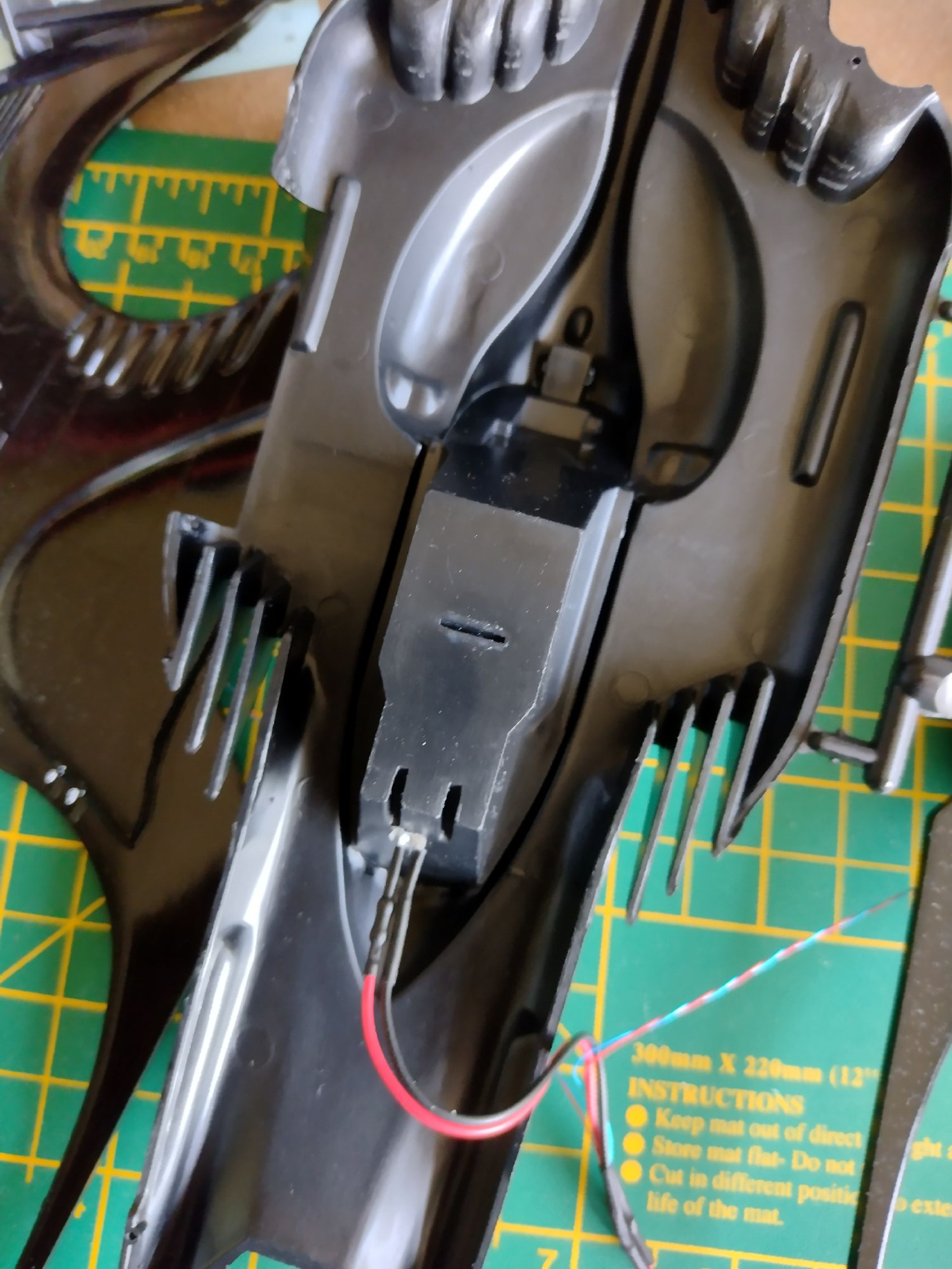
There is a single main wing light on either side of the model. For this step, you need to match up and clamp together (but not glue) the upper and lower section of each wing. A 2mm hole is then drilled centrally on the rear wall of where the clear light section will fit. This is to allow room for the wiring only, as the led is fitted in the clear section itself.
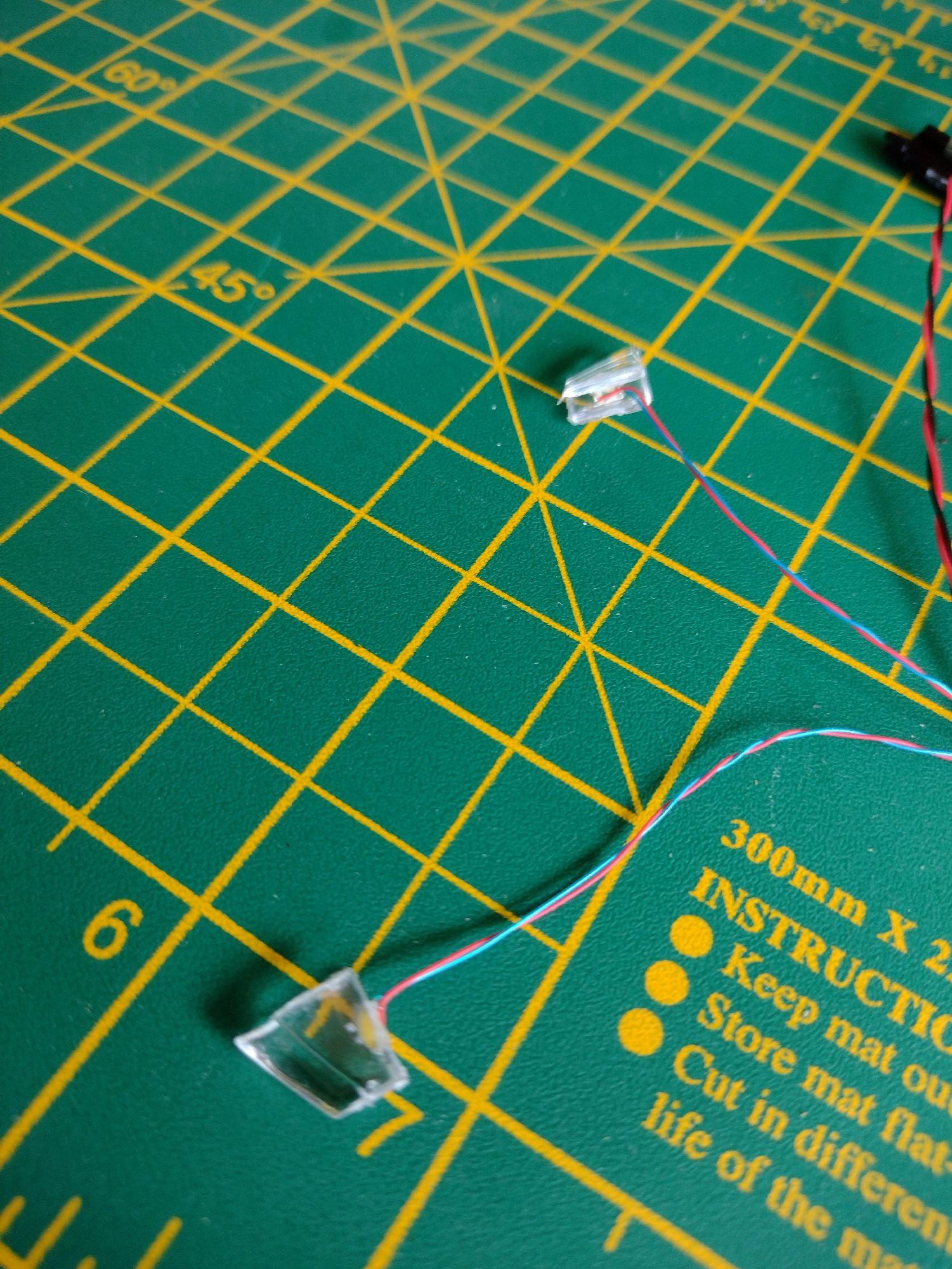
Wing Light Lenses
You will find that the wing light leds are an exact fit for the clear lens sections. Making sure the lens fitting is the correct way round, place them centrally flush to the rear and secure them with a drop of PVA glue. Don't be tempted to use poly cement or superglue, as this can fog the clear plastic and damage the led / wiring. Use PVA and return to the build the following day.
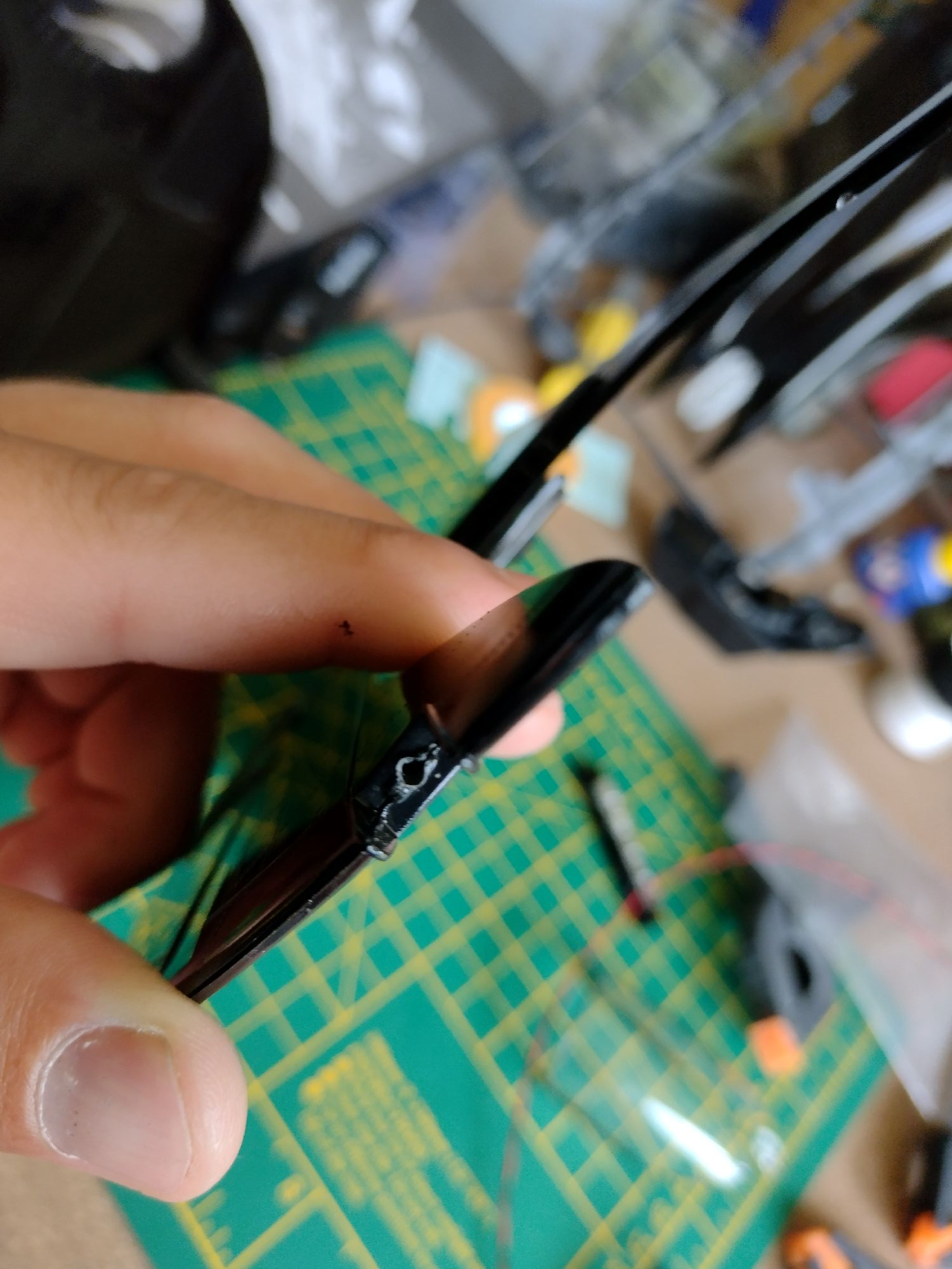
Fitting the wing halves together.
These leds have very fine wiring, and are easily routed between each wing half so that the exit at the centre of where the wings hook into the fuselage. For ease of fit, I always leave the clear led section proud, route the wires and then glue the wing halves together. When dry, simply push the wing light lenses into place. You can glue these with PVA if you wish, but you'll find that they are quite a tight fit, and only really need to be pushed into place to secure them.

The cockpit uplighter.
Complete all required paintwork to the cockpit section and canopy, and ensuring the rear part of the canopy is correctly fitted, glue the cockpit to the upper fuselage as per the kit instructions. Add the ultra violet 3mm led uplighter to the footwell as shown, and secure with a small drop of glue.
To finish
These are really all the main lighting modifications needed. Run the power lead of the set through the stand hole in the bottom fuselage, clip the wing sections into place, and secure with the upper half of the fuselage.There is plenty room inside the model to fold in the led wiring so that it's out of sight. Run the power lead seperately through the metal support tube, and then through the hole in the base. Push the metal support into the base first, then into the bottom of the fuselage.
Finally add the CR2032 battery holder and switch. Connect the red wire of the battery box to the red wire on the power lead, and black to black using the micro screw terminal connector. Note that unlike most connectors that push downwards to secure wiring, these connectors clamp the wires by moving upwards when tightened.
