
Revell Millennium Falcon - Fibre Optic Version
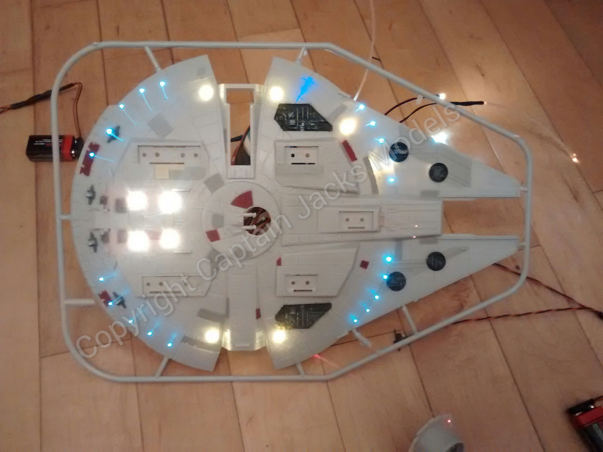
This is a great little light kit featuring more fibre optics than the original set.
As with the first light kit, it fits both the original Revell and the re-packaged Force Awakens version.
To save covering old ground in this guide, the following parts of the light kit are installed in exactly the same way as the previous instructional:
Click here for the previous Revell guide if needed
- The cockpit fibre optics & warm white uplighter.
- The central upper and lower clear section lights.
- The ramp warm white.
- The two front cool white headlights.
- The blue booster led strip.
- The power leads (models makers choice depending on how the model is to display)
The main difference with this set is a new landing light layout, and red lights for the side sections.
Drilling the underside of the model...
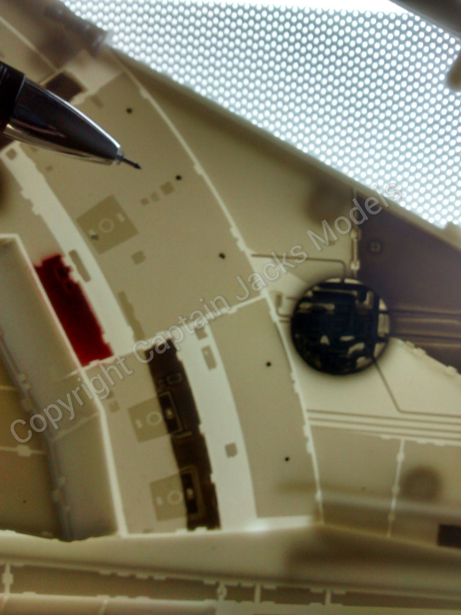
To install the new landing light layout, you will need a 1mm, 3mm and 5mm drill. To make marking the positions of the lights easier, again its advised to use the small dot stickers as per the previous guide. The fibre optic positions were marked using a fine liner.
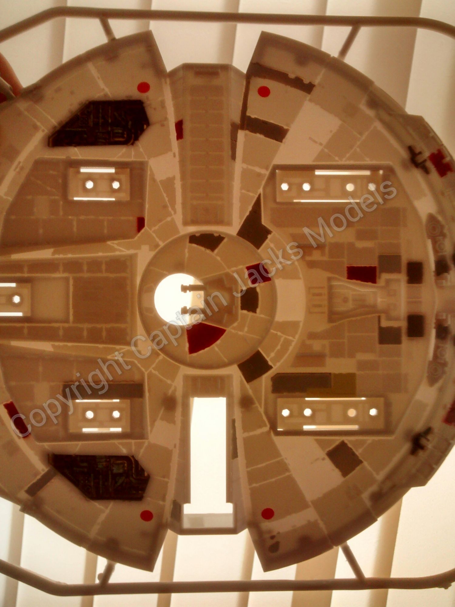
To ensure that the drilled holes will miss any important structural part of the model, its advised to hold the base up towards a light source eg window, or light box if you have one, so that you can see through the panel.
Step 1
Start by positioning the marks for the four 5mm warm whites, two on either side of the model. These need to be drilled with a 5mm drill
Step 2
Now its the same marking method for the four 3mm warm whites that are on the underside rear of the model. These need to be drilled with a 3mm drill.
Step 3
Now its time to mark out the positions of the cool white fibre optics. These are positioned as shown towards the outer edge, with five strands in each quarter of the circular base. A fine liner pen is ideal for marking the location of each strand, again using a light source to check everything is correct.
A good tip to get equal spacing of the bunch of five holes is to pick one quarter of the base, mark hole 1, then hole 5. The middle between these gives hole number 3, and the middle between these holes number 2 and 4.
Take your time marking out the fibre positions and always double check that they run inside the model shell, and not through any jointing clip sections. When you're happy with the layout, drill using a 1mm drill.
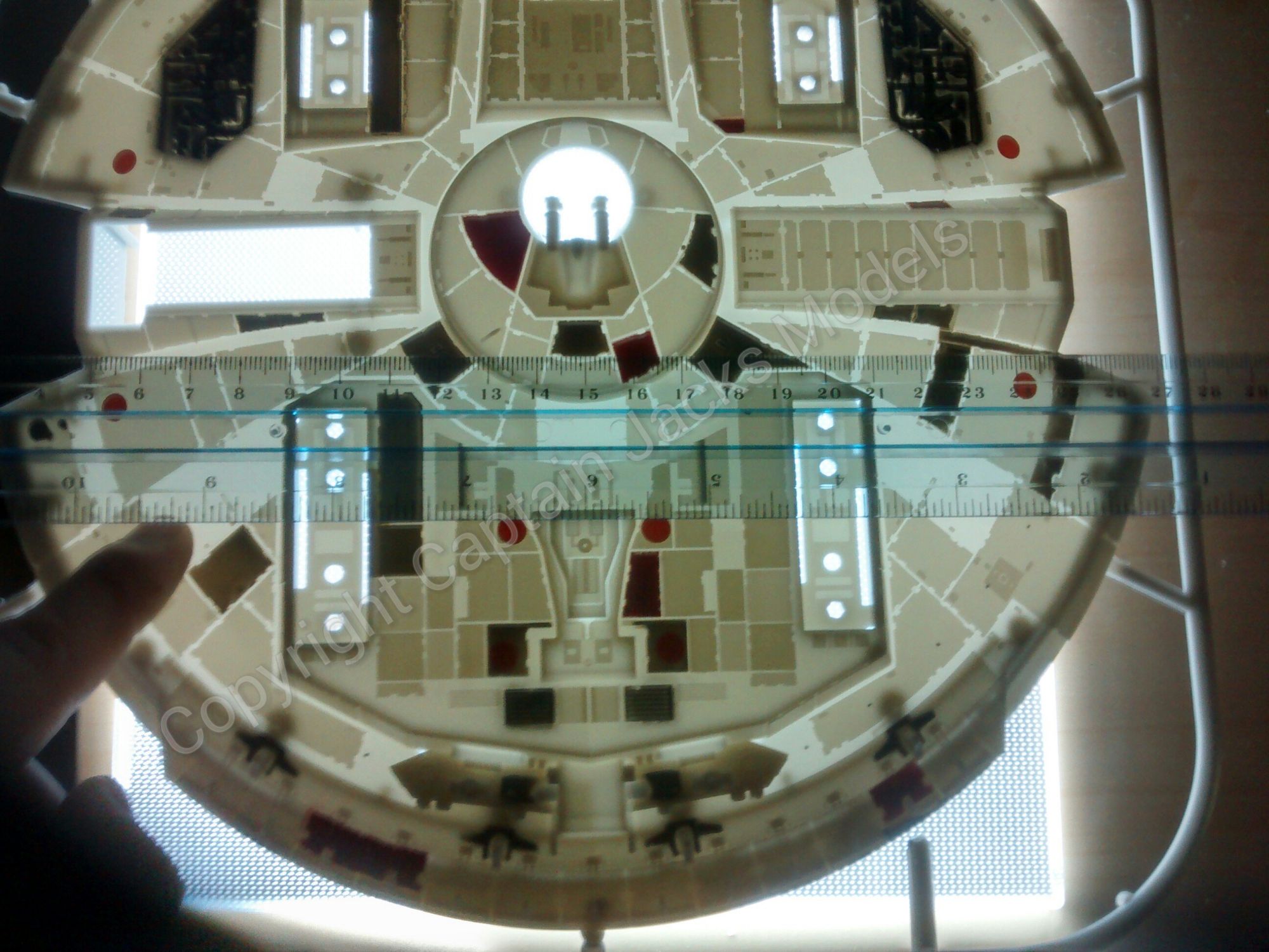
To ensure the starting point of each group of five holes align, its worth placing a straight edge across the model to make sure that everything is level.

Step 4
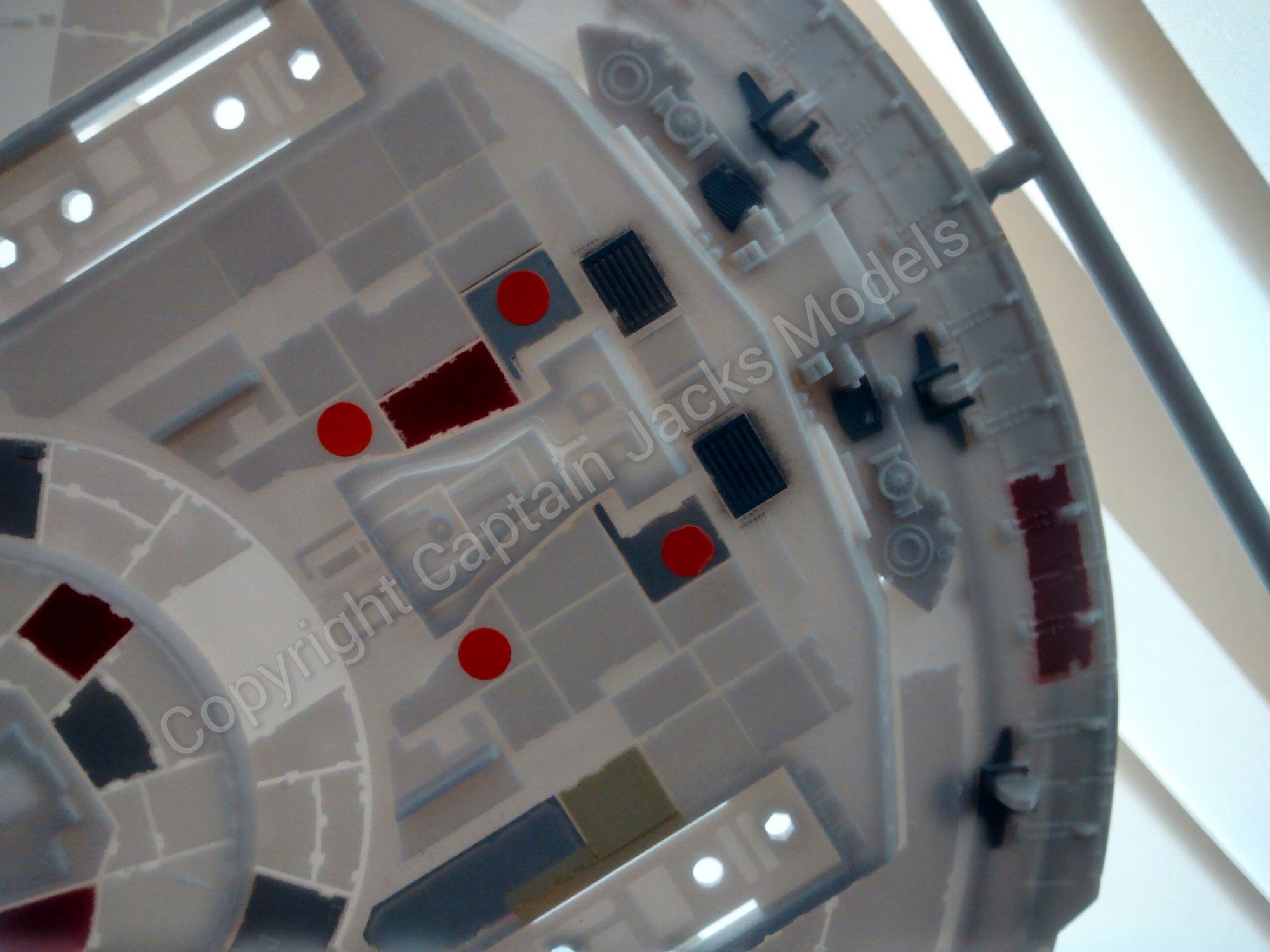
To complete the drilling process for the fibres, the two red underside front lights need to be drilled, along with the four corners of the two side panels as shown.


Step 5
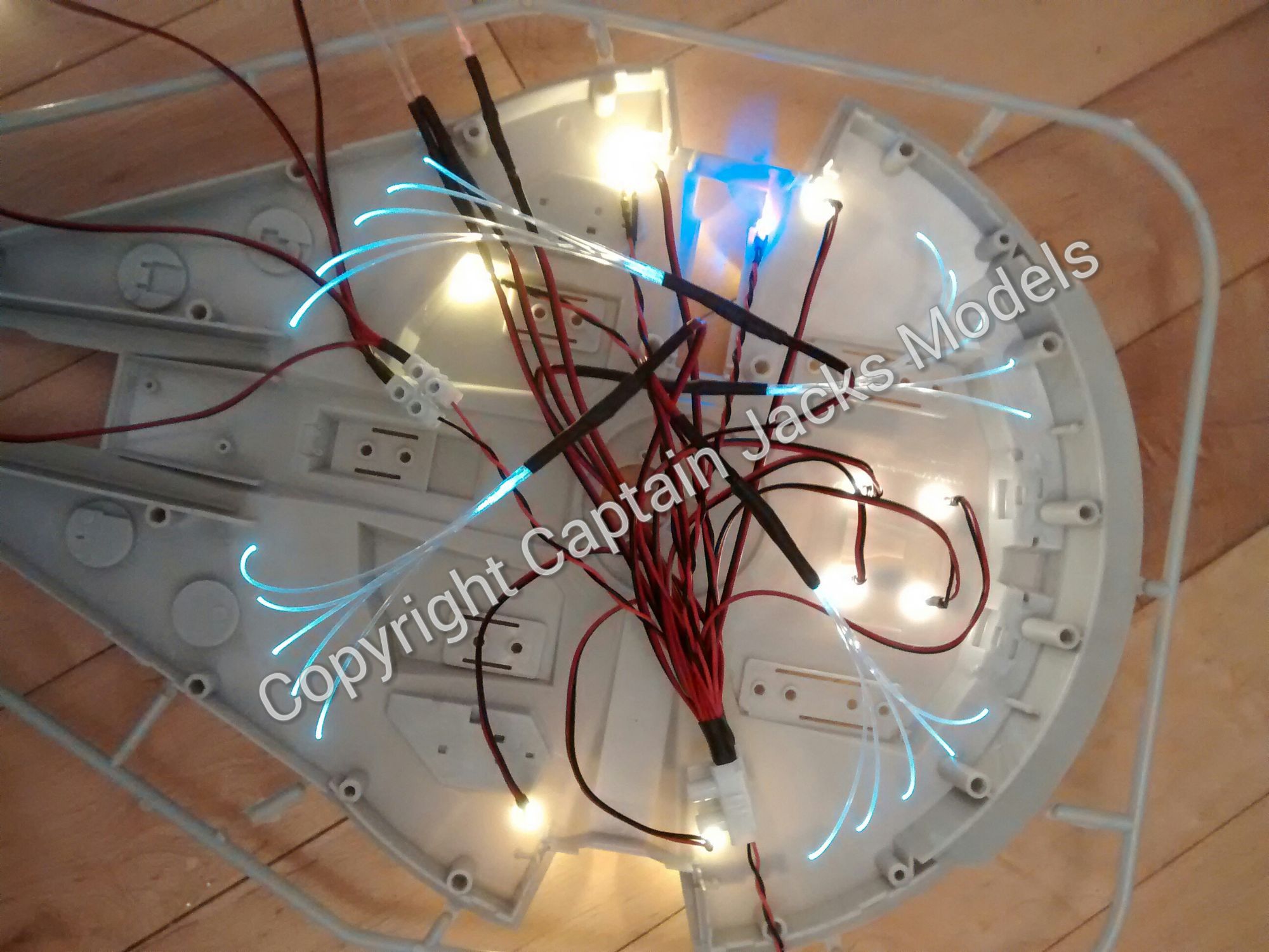
With the prep work completed, the leds and strands for the underside can now be fitted. Its helpful to install them in this order for ease of fit:
- The four 5mm warm whites.
- The ultra violet led for the central clear panel.
- The four 3mm warm whites - centre rear of base.
- The cool white fibre strands.
- The red front underside strands (the two strand unit)
- Both of the side panels with the four strand reds.
Continue to build the model and incorporate the light kit as per the previous guide. When 100% happy with the fibre fit, put a blob of glue on each one on the inside of the model shell to secure. Let this dry fully, and use flush cutters to trim the strands to length.
Step 6
Admire your work.... :)