
Poe's X-Wing Fighter

A great, very effective little kit, giving good scale size results.
The set is installed in a similar way to the larger Revell X-Wing as the layouts are very similar, however key points are listed below.
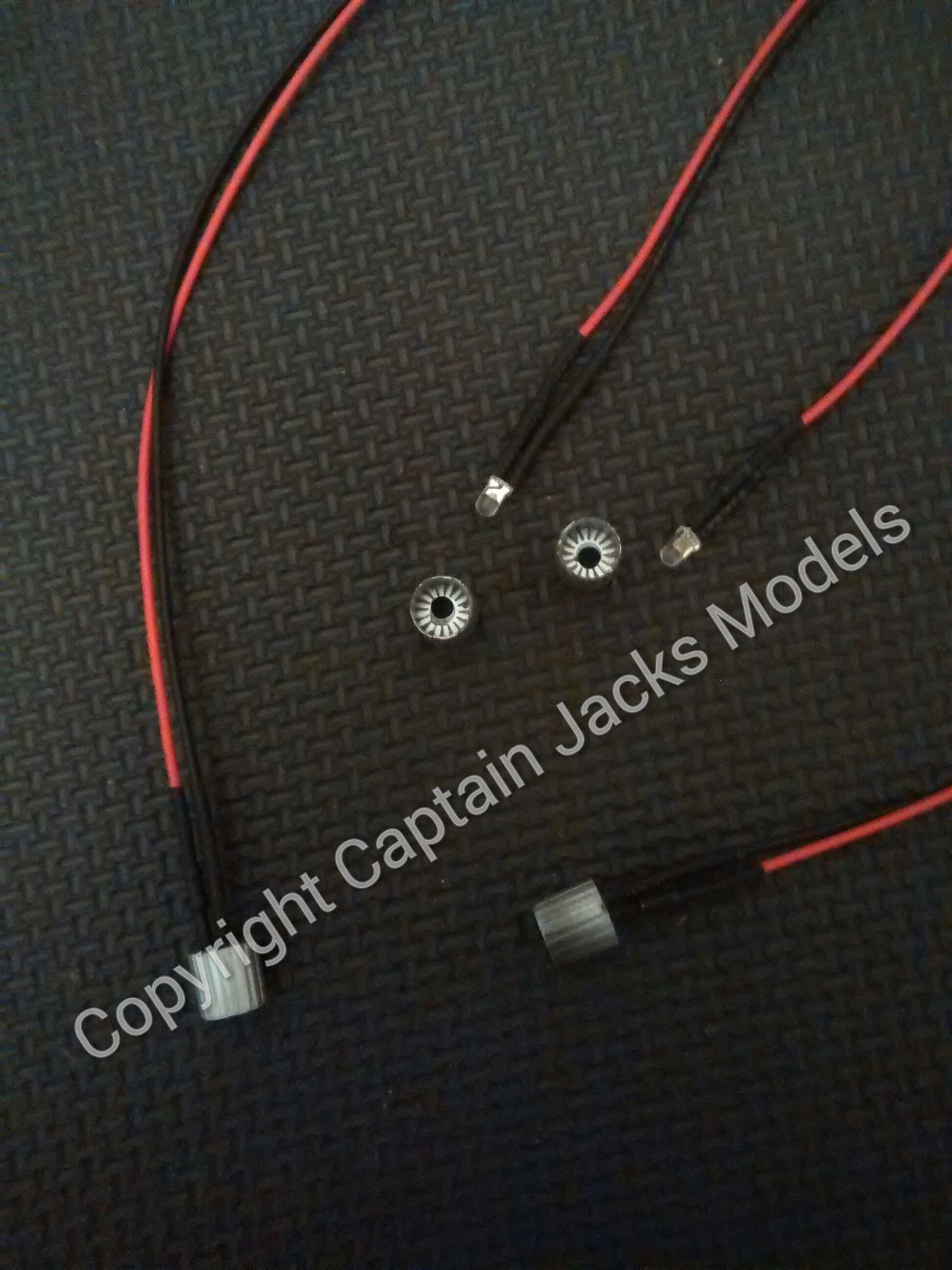
1) Start by drilling out the booster ends using a 3mm drill. Remove the four pink leds from the screw terminal connector, and insert the four pink led lenses into the booster end caps.
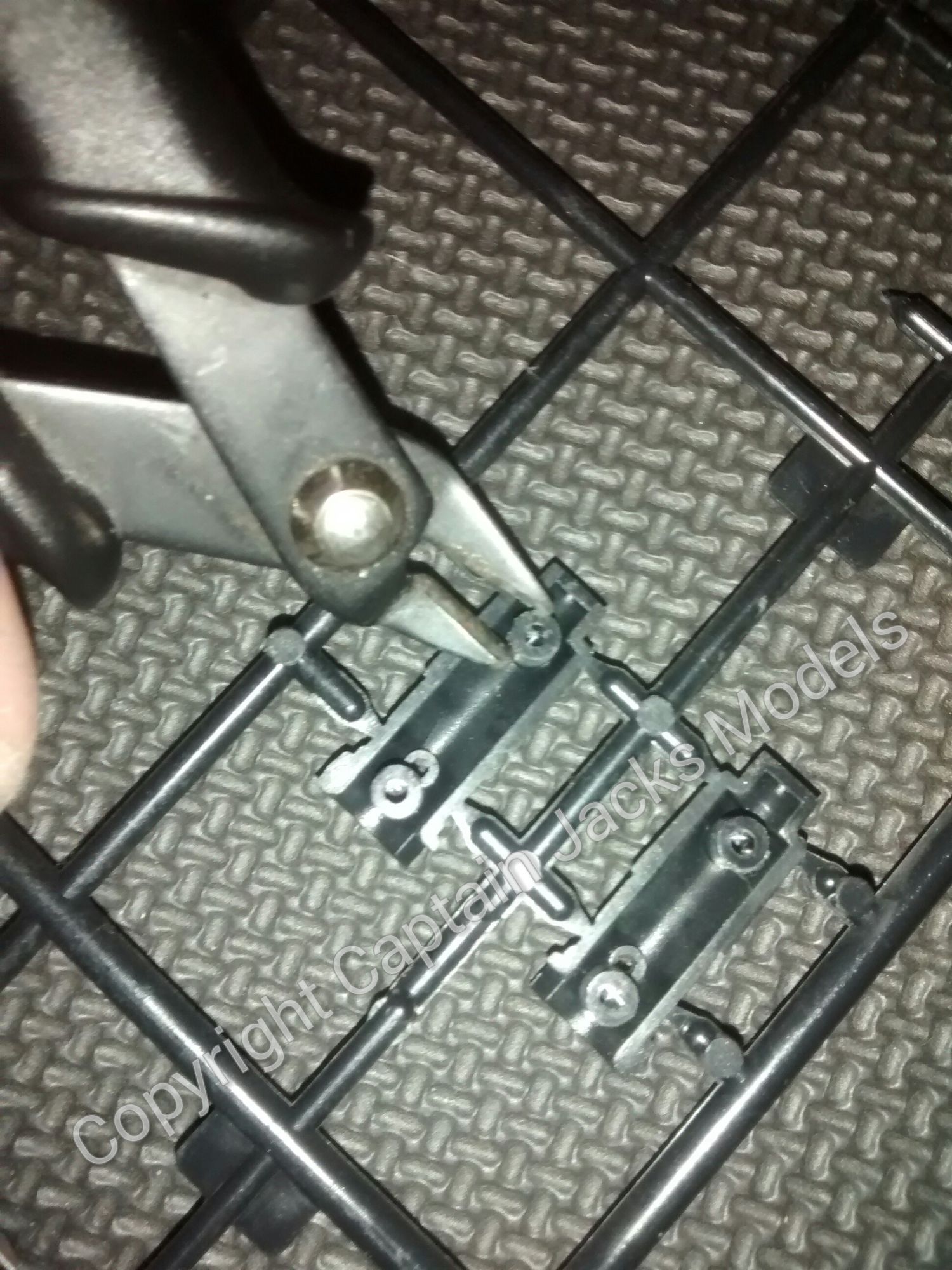
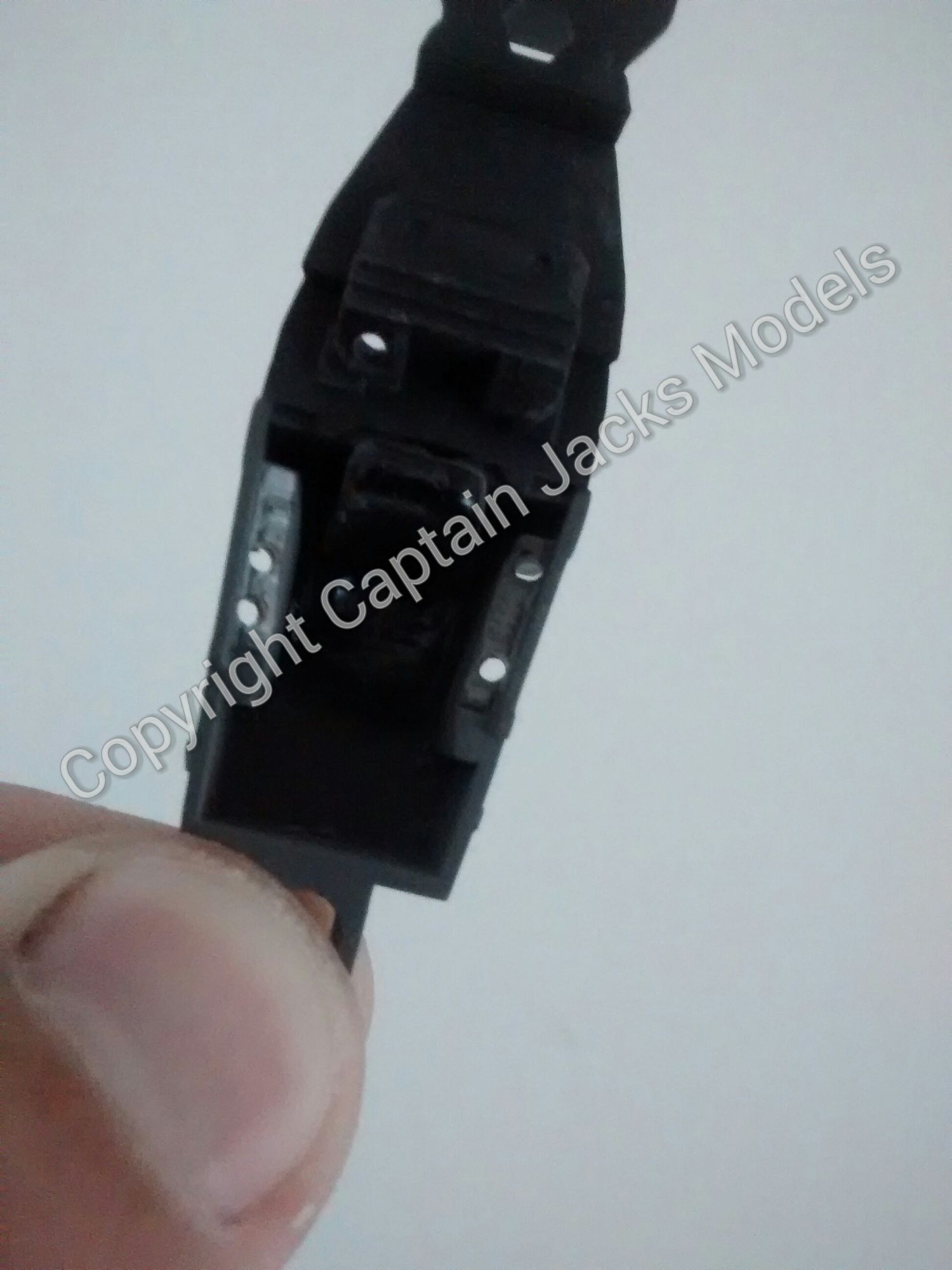
2) Cut out the pins on the inside of each booster arm to make room for the led wires. Use glue to affix the two halves instead of using the pins. Both half sections of each booster unit need to be clipped out to accommodate the wires.
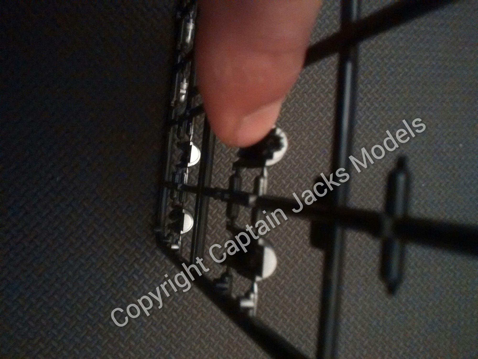
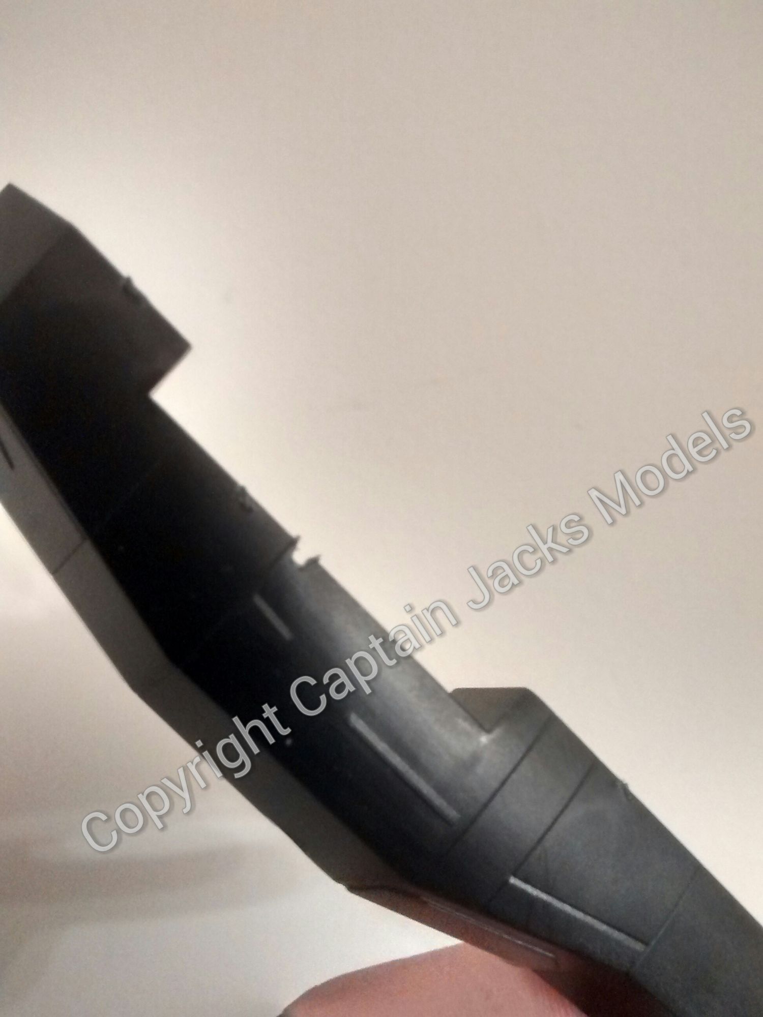
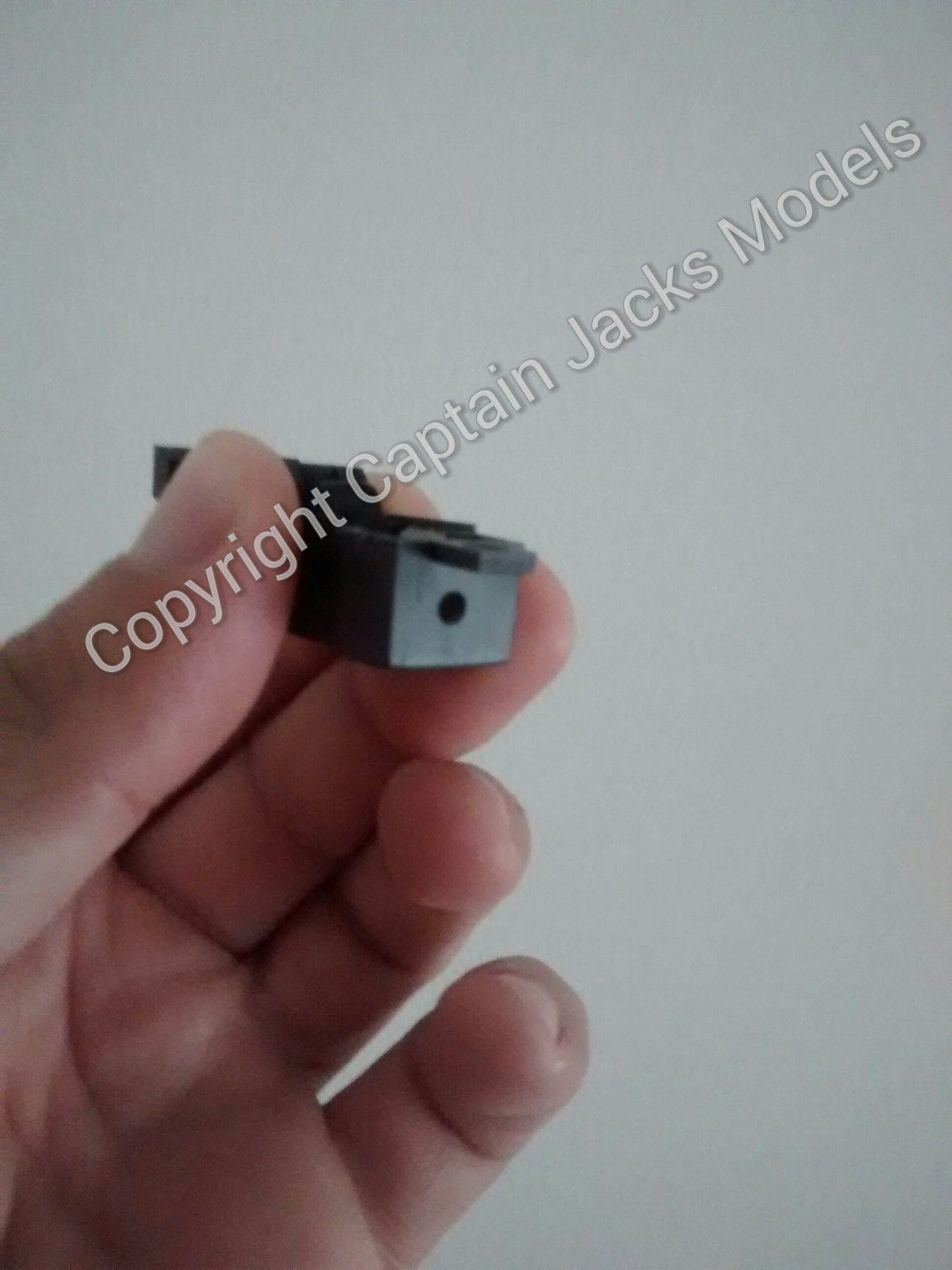
3) The end of the booster arm also needs a notch cutting in it to allow the wires to run through. You can see in the second photo how the led sits in the booster arm.
Take care when fitting the led in place. Do not push the led using the component legs - use a small flat blade screwdriver to push the led in from the base if needed.
4) Fit the wing panels together. The bottom sections of the wings require a 3mm drill hole as shown to route the wiring. X-Wings can be a little confusing with the way they fit together at the best of times, so ensure that the wing orientation is correct prior to drilling.
5) A corresponding hole in the lower half of the fuselage then needs to be clipped out to route the lower wing wires.
6) The top wings need a 3mm drill hole as close to the flat panel section as possible. There's no need to notch the fuselage for the top wing section.

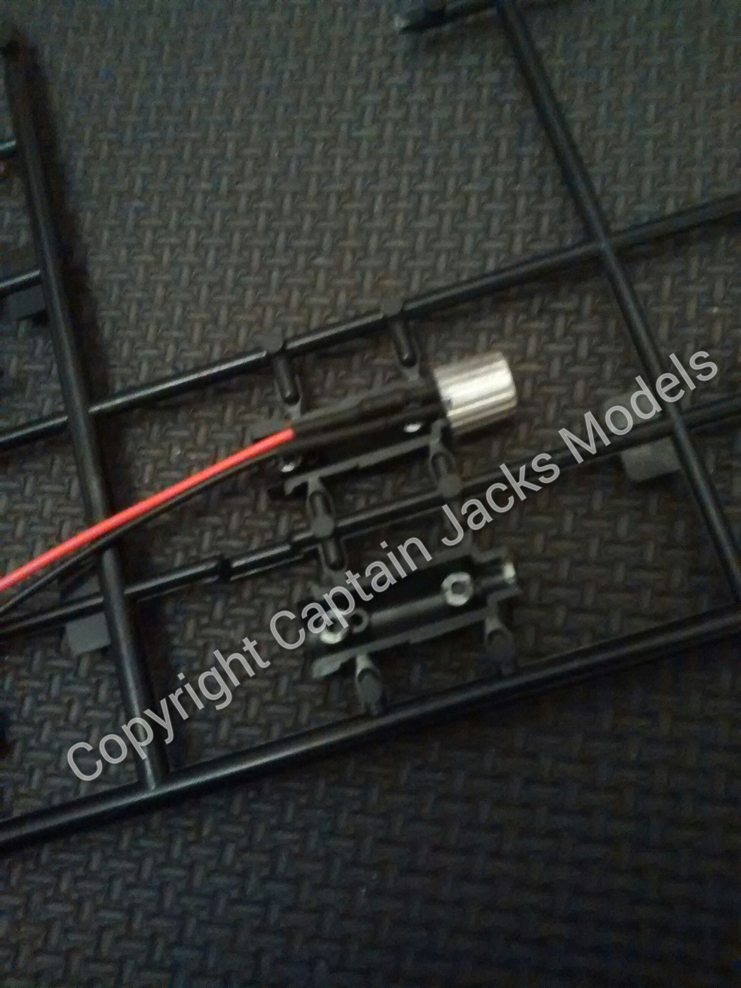
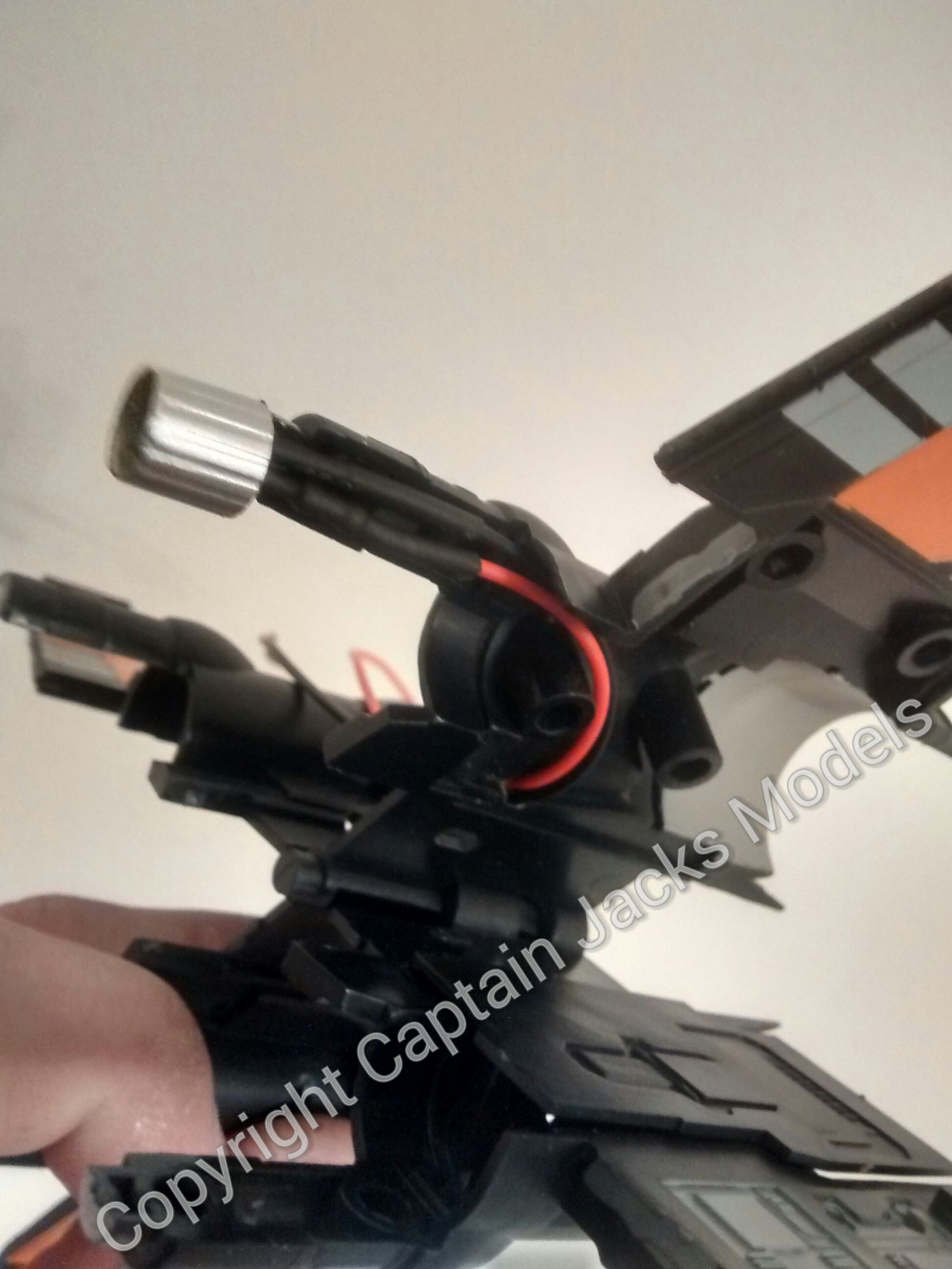
7) The booster arm backing plates also need roughly notching out to allow the wires to run through.
8) Assemble the wing panels as per the model kit instructions, routing the led wires through the upper and lower 3mm holes. When complete, twist the four red wires together, and then twist the four black wires together.

9) Cut a notch in the lower fuselage wing support as shown to route the bottom wing wires.
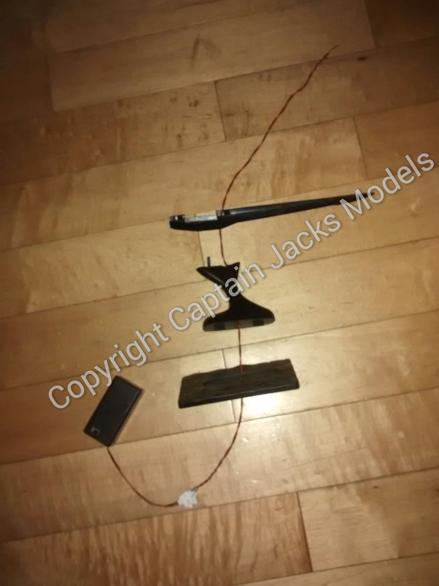
10) Now its time to fit the main power lead from the battery box. Clip the lower half of the fuselage onto the stand, and drill a 3mm hole through the fuselage and top of the stand for the lead. Next drill a 3mm hole in the base of the stand, making sure that its in line with the top holes. Feed the power lead through.
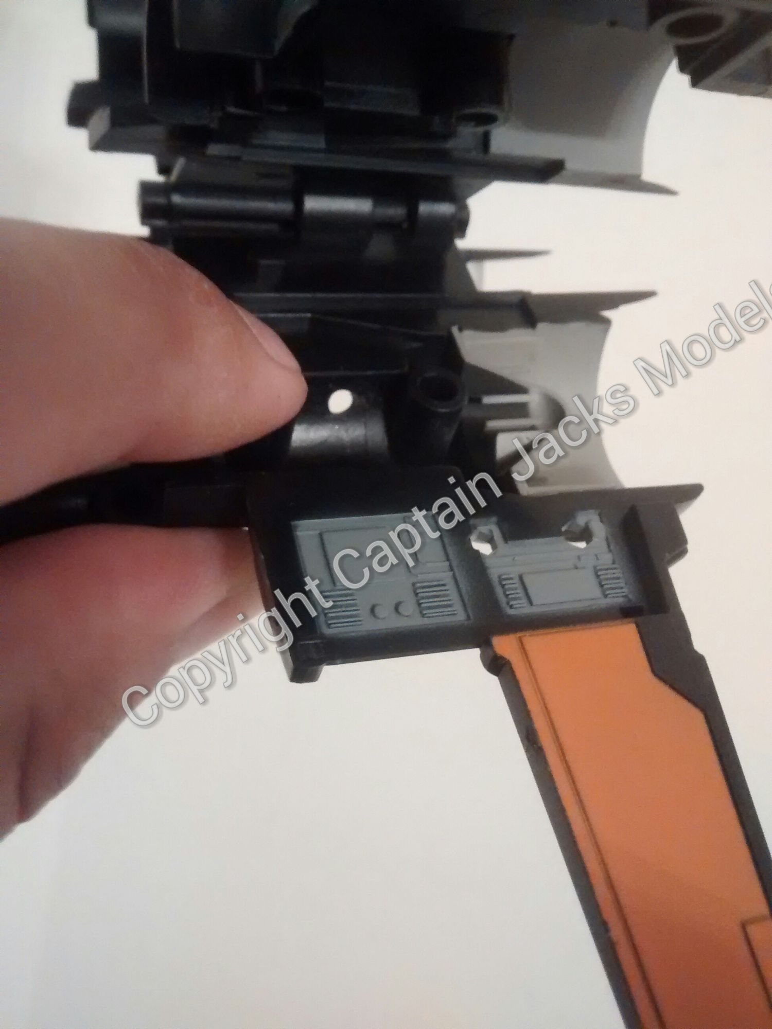
11) In the cockpit section, drill a 3mm hole in the front of the unit just above the pilots feet for the ultra violet up-lighter.
12) Drill five 1mm holes in the cockpit area in your chosen positions for the fibre strands. Feed the strands through to approximately half their length, and insert the ultra violet led. Glue the strands in place from the underside of the panel, and allow to dry fully. When dry, trim the fibres flush to the control panels.
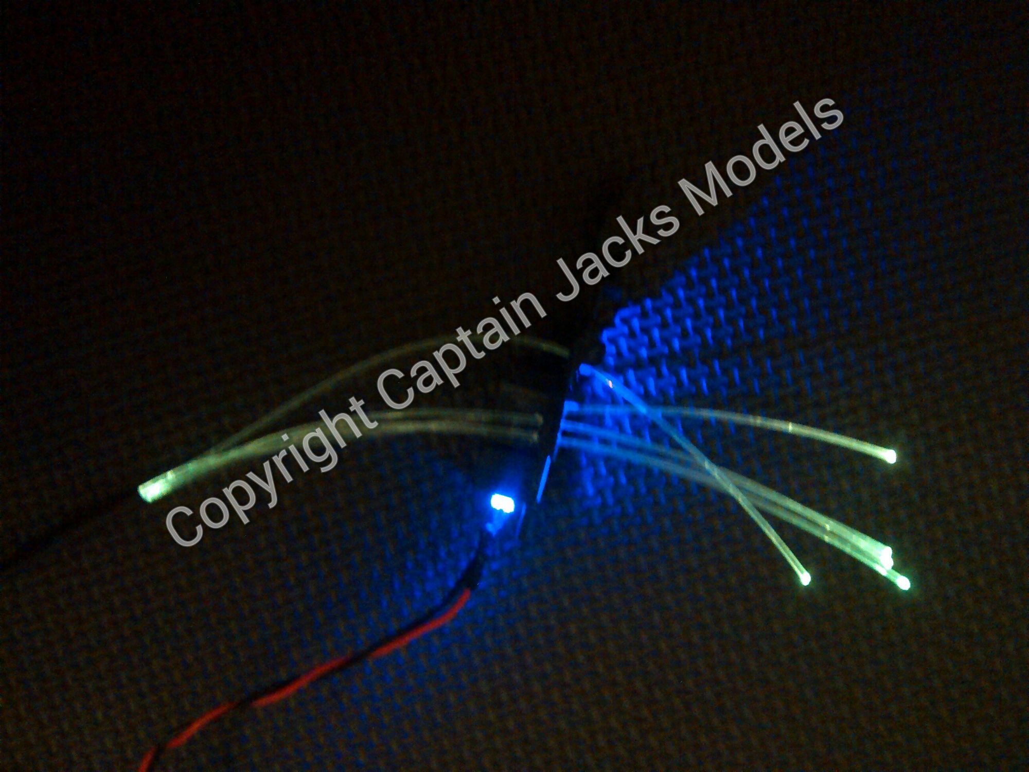
I use a small amount of superglue to secure the fibres firmly on the unseen part of the surface. Trim using flush cutters for the best effect.
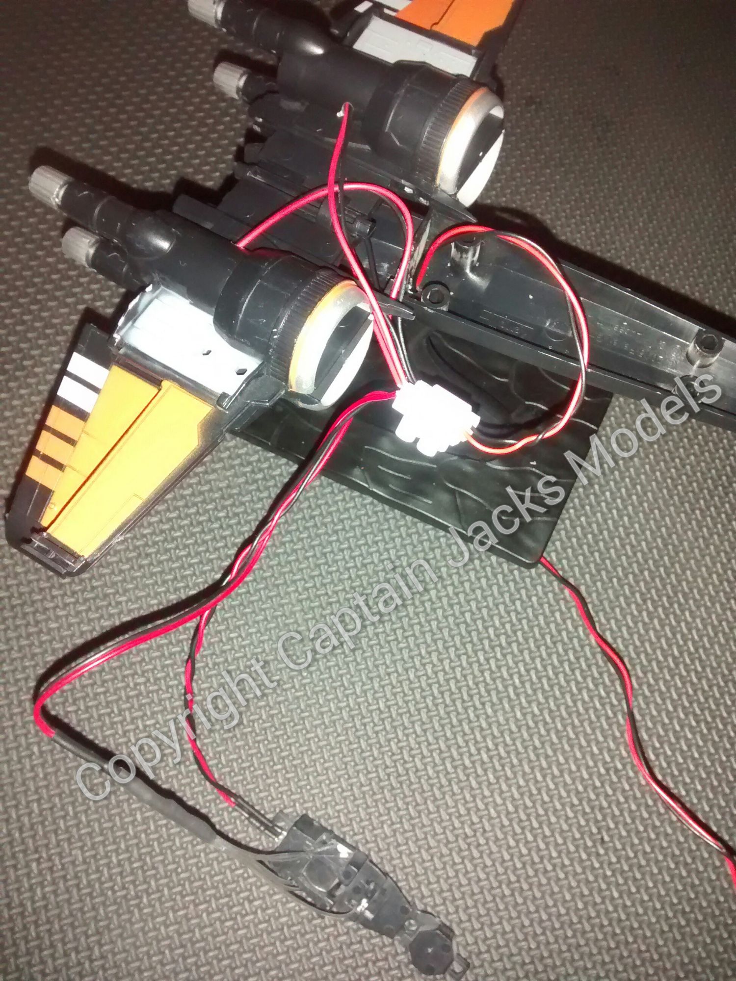
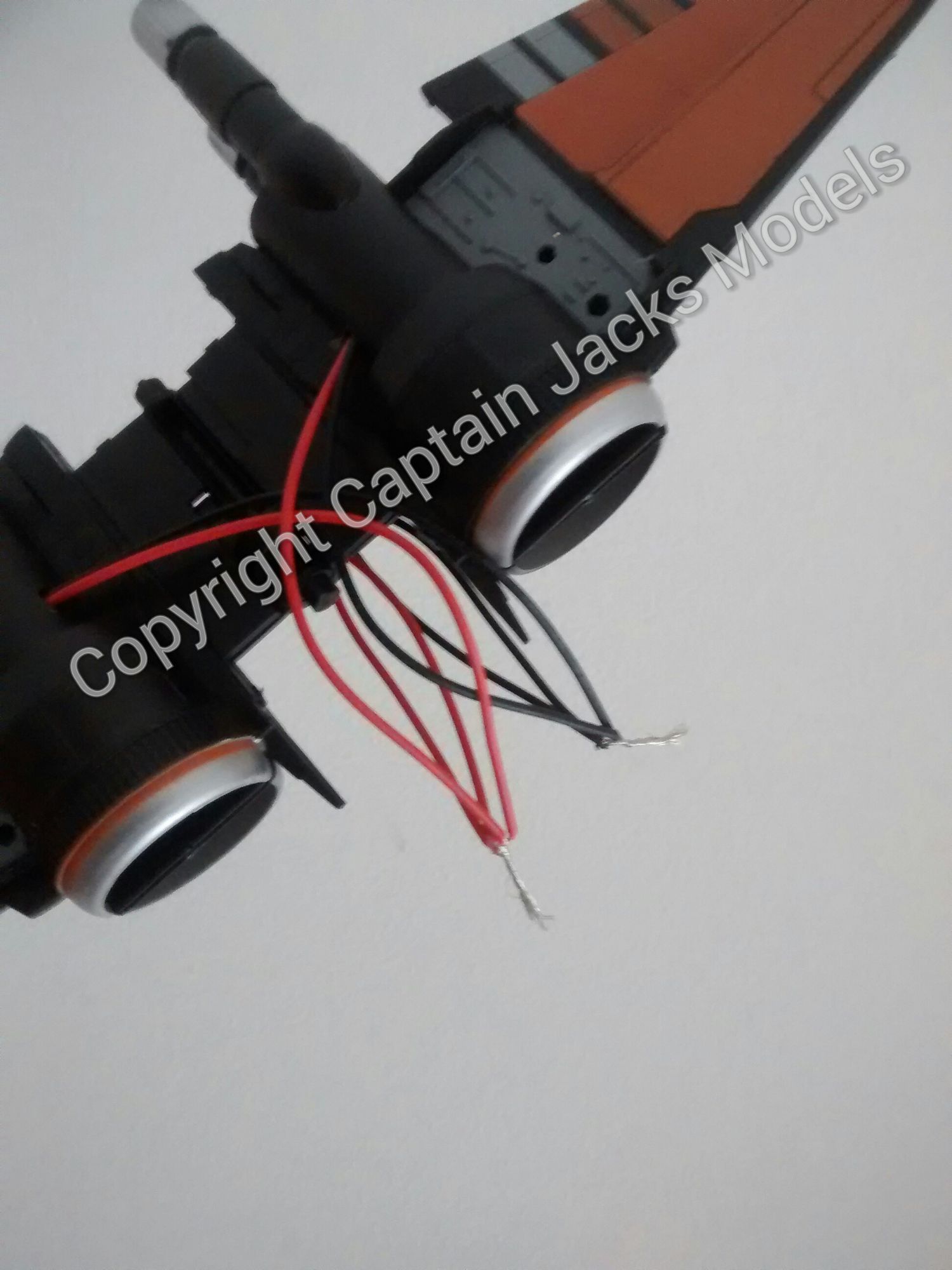
13) To connect the circuit together, join the red wires from the cockpit lighting to the red wires from the pink booster leds. Similarly join all of the black wires together.
Separate the two wire colours using the screw terminal connector. Run the power lead to the opposite side of the connector, matching red wire to the red side, and black to the black.
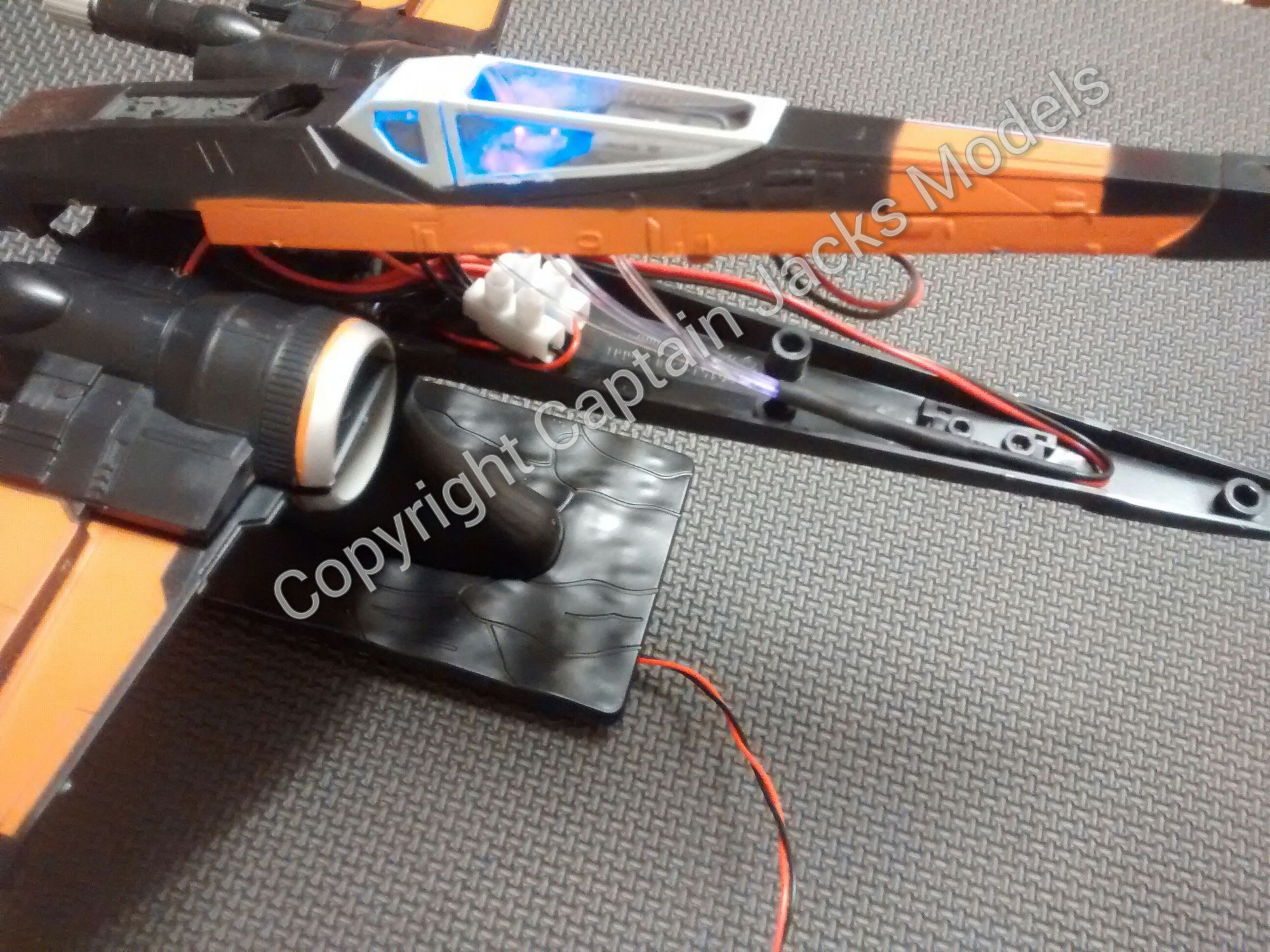
14) Place the wing section into position, carefully ensuring all wiring is routed correctly. Fix the cockpit interior to the upper fuselage, and clip down the upper fuselage to complete the model. The photo show how best to position the fibre bundle in the nose of the craft.
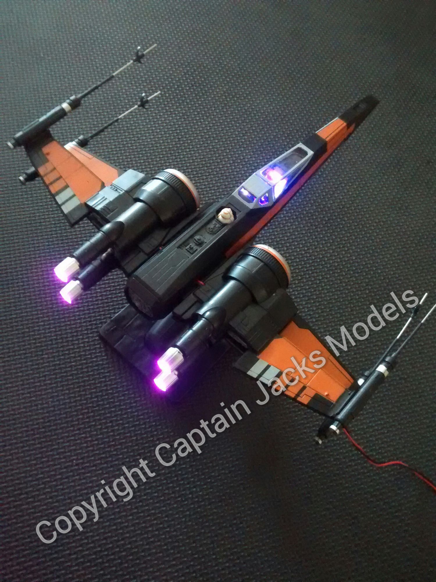
Another great X-Wing Fighter completed! Check out the Instagram and Facebook page feeds for the video of the completed model.