
Revell 06658 Millennium Falcon

There are many ways to install this light kit depending on the model builders personal preference. The layout shown above is the most popular and my favourite. You can include as many or as few of the modifications as you wish.
The leds in the main system are installed by drilling 3mm holes in the base of the model where required. The leds will then neatly push into place. You can either use the picture above as a guide or design your own layout. A 3mm hole can also be drilled for both main power leads if they are to be run to the battery outside the model eg in a display base.
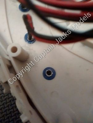
A good tip is to use small dot stickers - the type you can buy from most newsagents - to position each led prior to drilling the hole. This makes it so much easier to see the light placement, and they also act as a key for the drill.
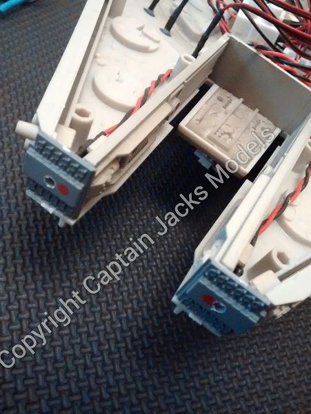
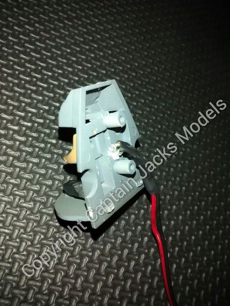
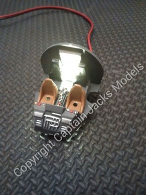
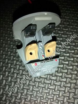
For the forward facing lights, I've opted for two cool whites as the main beams, and two reds on the underside. Again these are all still 3mm holes - easiest to drill after the two grey panels have been glued into place. Line up the drill holes with the spaces inside the model, instead of going for the red dots on the panels as the leds won't align otherwise.
If you look back at the main photo, you'll see that the cool whites show up as a light blue on the photo itself.
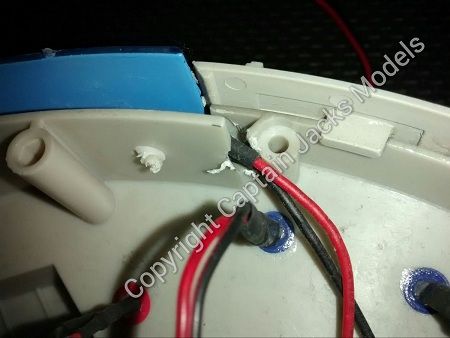
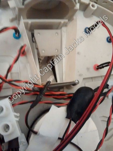
The blue booster light strip is quite straight forward to fit and needs minimal modification. You will need to drill a small hole for the power lead to run out of the model.
The light strip itself has an adhesive backing and fits to the grey panel just inside the blue panel provided with the kit. The fixing tape is strong, but I always glue it at either end to ensure a permanent fit. The only real modification here, is to cut a small notch using snips to allow the power leads to the strip to fit in place - see the photo above.
Do not attempt to run the strip leds and main lighting circuit from a single battery. The strip uses considerably more power, and will shut down the other leds.
One of the main things that I get asked is how to install the cockpit light and fibre optics. Again the answer is that there are no hard and fast rules - you can go into as much or as little detail here as you wish. That's the beauty of model building!
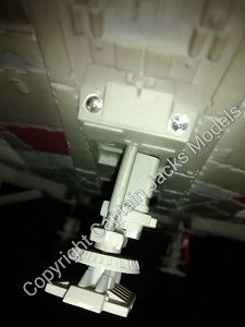
My personal preference is to drill a 3mm hole through the base of the cockpit floor, pointing to the back of the seats, for the warm white to illuminate the rear part of the area. Background lighting here works better if its more subtle, as opposed to an upward or forward facing led that gives the area a "radioactive" glow :)
The fiber optics can be fitted on the control panels where required. I like to fit them on the central section which divides the two seats. To fit the fibers, you need to carefully drill 1mm holes where you would like to fit each strand. The fiber we use is the most supple, but bend the fiber slowly to reduce the risk of snapping it.
Run each strand through the fitting hole so that it is proud, and then place a small blob of glue on the unseen section of the panel through which it runs.
Let the glue dry thoroughly.
When the glue has dried, use snips or ideally flush cutters to cut off the excess fiber on the seen section protruding through the panel for a neat fit.
There's more advice on using fiber optics in the hints n tips section of the site if needed.
That's pretty much the basics covered. Remember, it's your build, so don't be afraid to try out new ideas with it. The whole idea is to have fun, and there's not always the need to get lost in a technical world of precision - the simple ideas are often the best!
Use the terminal connectors to move lighting around, fit power leads and even add more leds if you wish.
If you get stuck with anything, you can also drop me an email and I'll advise as best I can.